Configuring multi-area OSPF with Ansible
This time we're going to configure OSPF, but not with the CLI, we're going to use a network automation tool called Ansible. I'm going to walk through the steps how we can configure a relatively simple multi-area topology just with Ansible.
Ansible is an agentless network automation tool, it doesn't require any special software to run on the managed nodes (aka. on the routers). It uses SSH as a transport to connect to the network devices and it pushes the desired configuration to them. We write the tasks in a YAML file called Playbook usually defining the end-state in a declarative approach, which then Ansible analyses and then takes the required actions and makes configuration changes. This time we're going to use GNS3 with the following topology:
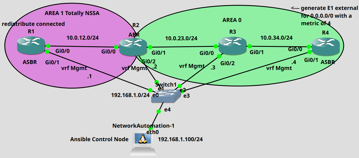
We're going to use a Linux machine as a Control Node which runs as a Docker container instance in GNS3 and already has Ansible installed. I've already configured the IP addresses on the devices and created a Mgmt VRF on all of the routers. These interfaces are in the common subnet 192.168.1.0/24, we're going to use these interfaces to SSH into the routers, because there's obviously no routing established yet between the routers. Notice that these interfaces are not in the global routing table, so the OSPF configuration won't affect them, we're only going to configure the interfaces in the global routing table. So first let's assign an IP address to the Control Node as well:
root@NetworkAutomation-1:~/ansible_lab# ifconfig eth0 192.168.1.100 netmask 255.255.255.0 up
Next we need to enable SSH on all routers, and create a user with privilege level 15. To enable SSH we have to generate an RSA cryptographic key pair first. To be able to do that we also have to assign a domain name to the routers first, this is how we do it on R1:
R1(config)#ip domain name test.comR1(config)#crypto key generate rsa mod 2048The name for the keys will be: R1.test.com% The key modulus size is 2048 bits% Generating 2048 bit RSA keys, keys will be non-exportable...[OK] (elapsed time was 1 seconds)%SSH-5-ENABLED: SSH 1.99 has been enabled
Next we enable SSH on the first five vty lines and we use the local database for authentication:
R1(config)#line vty 0 4R1(config-line)#transport input sshR1(config-line)#login localR1(config)#username ansible priv 15 secret cisco
Now we create the Inventory or the hosts file in other words on the Control Node, this is where we list all of the devices and the characteristics of the devices:
[routers]R1 ansible_host=192.168.1.1R2 ansible_host=192.168.1.2R3 ansible_host=192.168.1.3R4 ansible_host=192.168.1.4[routers:vars]ansible_connection=network_cliansible_network_os=iosansible_user=ansibleansible_password=cisco
In this case I assign an alias to all to the routers: R1 is 192.168.1.1, R2 is 192.168.1.2 etc. In the [routers:vars] section we have some variables which are common for all of the devices: these are all Cisco IOS routers, and we use SSH to connect to the routers with the same username (ansible) and password (cisco). We can also write this in YAML if we want, here I choose to use the regular INI format.
Feel free to download this, and also every other YAML file related to this lab from my Git repository.
If we don't have all of the public SSH host keys from all of the device in the .ssh/known_hosts file on our Control Node, it can be advantageous to turn off the host_key_checking on the Linux host, otherwise Ansible won't run the playbooks. Ansible uses the following global configuration file: /etc/ansible/ansible.cfg, here we can turn it off:
[defaults]host_key_checking=False
Just search for the line and uncomment it, or write it under the [defaults] section. Before writing the playbooks, let's check if we can actually reach our routers defined in the hosts file:
root@NetworkAutomation-1:~/ansible_lab# ansible routers -m ping -i hostsR4 | SUCCESS => {"changed": false,"ping": "pong"}R1 | SUCCESS => {"changed": false,"ping": "pong"}R2 | SUCCESS => {"changed": false,"ping": "pong"}R3 | SUCCESS => {"changed": false,"ping": "pong"}
We can also gather some information from our routers with the following command before running the actual playbook:
root@NetworkAutomation-1:~/ansible_lab# ansible routers -m ios_facts -i hostsR1 | SUCCESS => {"ansible_facts": {"ansible_net_api": "cliconf","ansible_net_gather_network_resources": [],"ansible_net_gather_subset": ["default"],"ansible_net_hostname": "R1","ansible_net_image": "flash0:/vios-adventerprisek9-m","ansible_net_iostype": "IOS","ansible_net_model": "IOSv","ansible_net_operatingmode": "autonomous","ansible_net_python_version": "3.8.5","ansible_net_serialnum": "9H24ZY0WDM1GYI1FBLGYZ","ansible_net_system": "ios","ansible_net_version": "15.6(2)T","ansible_network_resources": {}},"changed": false}R2 | SUCCESS => {"ansible_facts": {"ansible_net_api": "cliconf","ansible_net_gather_network_resources": [],"ansible_net_gather_subset": ["default"],"ansible_net_hostname": "R2","ansible_net_image": "flash0:/vios-adventerprisek9-m","ansible_net_iostype": "IOS","ansible_net_model": "IOSv","ansible_net_operatingmode": "autonomous","ansible_net_python_version": "3.8.5","ansible_net_serialnum": "99U0TV7PNS827AOMV8VWM","ansible_net_system": "ios","ansible_net_version": "15.6(2)T","ansible_network_resources": {}},"changed": false}R3 | SUCCESS => {"ansible_facts": {"ansible_net_api": "cliconf","ansible_net_gather_network_resources": [],"ansible_net_gather_subset": ["default"],"ansible_net_hostname": "R3","ansible_net_image": "flash0:/vios-adventerprisek9-m","ansible_net_iostype": "IOS","ansible_net_model": "IOSv","ansible_net_operatingmode": "autonomous","ansible_net_python_version": "3.8.5","ansible_net_serialnum": "9A0INR4IAY5JPCZE1N7UI","ansible_net_system": "ios","ansible_net_version": "15.6(2)T","ansible_network_resources": {}},"changed": false}R4 | SUCCESS => {"ansible_facts": {"ansible_net_api": "cliconf","ansible_net_gather_network_resources": [],"ansible_net_gather_subset": ["default"],"ansible_net_hostname": "R4","ansible_net_image": "flash0:/vios-adventerprisek9-m","ansible_net_iostype": "IOS","ansible_net_model": "IOSv","ansible_net_operatingmode": "autonomous","ansible_net_python_version": "3.8.5","ansible_net_serialnum": "9HDG0VKB6SJWEJNQ63JR7","ansible_net_system": "ios","ansible_net_version": "15.6(2)T","ansible_network_resources": {}},"changed": false}
Next let's write our playbook in YAML. If you're using a Linux machine without GUI, just as I do in this example, don't try to write YAML in vim or nano! Instead write it in VS Code or any kind of editor for syntax checking, indentation is very important in YAML, if you miss a space, Ansible simply won't run the playbook.
So we need the following requirements for the topology above: R4 should be configured as an ASBR, advertising the 0.0.0.0/0 default route as an E1 route with a metric of 4. There is no default route present in the RIB of R4, so we also need the always keyword as well, the command would be default-information originate always if we were using the CLI. R3 is just a regular backbone router with no additional configuration. R2 is an ABR, and we should configure area 1 as a Totally Not-So-Stubby area, so we need the no-summary keyword on the ABR. R1 is also an ASBR in the NSSA area which should redistribute his connected routes into the NSSA area. We have one additional connected route on R1 which is not advertised by OSPF: his loopback1 address which is 11.11.11.11/32. So after converging we should have an O N2 route on the ABR which will be converted into O E2 when it is injected into the backbone. Additionally on every router we set the reference bandwidth to 100 Gbps, so every interface should have a cost of 100.
---- hosts: R4tasks:- name: Configuring OSPF on R4cisco.ios.ios_ospfv2:config:processes:- process_id: 1areas:- area_id: "0"network:- address: 0.0.0.0wildcard_bits: 255.255.255.255area: 0default_information:originate: truealways: truemetric_type: 1metric: 4auto_cost:reference_bandwidth: 100000- hosts: R3tasks:- name: Configuring OSPF on R3cisco.ios.ios_ospfv2:config:processes:- process_id: 1areas:- area_id: "0"network:- address: 0.0.0.0wildcard_bits: 255.255.255.255area: 0auto_cost:reference_bandwidth: 100000- hosts: R2tasks:- name: Configuring OSPF on R2cisco.ios.ios_ospfv2:config:processes:- process_id: 1areas:- area_id: "0"- area_id: "1"nssa:no_summary: trueset: truenetwork:- address: 10.0.23.0wildcard_bits: 0.0.0.255area: 0- address: 2.2.2.2wildcard_bits: 0.0.0.0area: 0- address: 10.0.12.0wildcard_bits: 0.0.0.255area: 1auto_cost:reference_bandwidth: 100000- hosts: R1tasks:- name: Configuring OSPF on R1cisco.ios.ios_ospfv2:config:processes:- process_id: 1areas:- area_id: "1"nssa:set: truenetwork:- address: 10.0.12.0wildcard_bits: 0.0.0.255area: 1- address: 1.1.1.1wildcard_bits: 0.0.0.0area: 1auto_cost:reference_bandwidth: 100000state: overridden- name: Redistributing connected routes on R1cisco.ios.ios_config:lines:- router ospf 1- redistribute connected subnetsparents: router ospf 1
You shouldn't memorize all of these syntax, we just have to use the documentation of the cisco.ios.ios_ospfv2 module. It shows how we should do the indentation, what keyword we should use and also has some examples at the end. Besides the cisco.ios.ios_ospfv2 I also had to use another module called cisco.ios.ios_configfor the redistribution. Here we have all of the IOS modules. So let's run the playbook:
root@NetworkAutomation-1:~/ansible_lab# ansible-playbook playbook_ospf.yaml -i hostsPLAY [R4] *******************************************************************************TASK [Gathering Facts] *******************************************************************************ok: [R4]TASK [Configuring OSPF on R4] *******************************************************************************changed: [R4]PLAY [R3] *******************************************************************************TASK [Gathering Facts] *******************************************************************************ok: [R3]TASK [Configuring OSPF on R3] *******************************************************************************changed: [R3]PLAY [R2] *******************************************************************************TASK [Gathering Facts] *******************************************************************************ok: [R2]TASK [Configuring OSPF on R2] *******************************************************************************changed: [R2]PLAY [R1] *******************************************************************************TASK [Gathering Facts] *******************************************************************************ok: [R1]TASK [Configuring OSPF on R1] *******************************************************************************changed: [R1]TASK [Redistributing connected routes on R1] *******************************************************************************changed: [R1]PLAY RECAP *******************************************************************************R1 : ok=3 changed=2 unreachable=0 failed=0 skipped=0 rescued=0 ignored=0R2 : ok=2 changed=1 unreachable=0 failed=0 skipped=0 rescued=0 ignored=0R3 : ok=2 changed=1 unreachable=0 failed=0 skipped=0 rescued=0 ignored=0R4 : ok=2 changed=1 unreachable=0 failed=0 skipped=0 rescued=0 ignored=0
It looks like Ansible successfully finished the tasks and made the configuration changes.
Verfication
Now let's use the CLI and take a look at the OSPF configuration of each router:
R1#show run | sec ospfrouter ospf 1 auto-cost reference-bandwidth 100000 area 1 nssa redistribute connected subnets network 1.1.1.1 0.0.0.0 area 1 network 10.0.12.0 0.0.0.255 area 1R2#show run | sec ospfrouter ospf 1 auto-cost reference-bandwidth 100000 area 1 nssa no-summary network 2.2.2.2 0.0.0.0 area 0 network 10.0.12.0 0.0.0.255 area 1 network 10.0.23.0 0.0.0.255 area 0R3#show run | sec ospfrouter ospf 1 auto-cost reference-bandwidth 100000 network 0.0.0.0 255.255.255.255 area 0R4#show run | sec ospfrouter ospf 1 auto-cost reference-bandwidth 100000 network 0.0.0.0 255.255.255.255 area 0 default-information originate always metric 4 metric-type 1
This is what we wanted to configure with the YAML file. Let's also verify the LSDBs and the routing tables. R1 should generate a single Type-7 NSSA external LSA for the 11.11.11.11/32 prefix:
R1#show ip ospf database nssa-external OSPF Router with ID (11.11.11.11) (Process ID 1) Type-7 AS External Link States (Area 1) LS age: 513 Options: (No TOS-capability, Type 7/5 translation, DC, Upward) LS Type: AS External Link Link State ID: 11.11.11.11 (External Network Number ) Advertising Router: 11.11.11.11 LS Seq Number: 80000001 Checksum: 0x3EFB Length: 36 Network Mask: /32 Metric Type: 2 (Larger than any link state path) MTID: 0 Metric: 20 Forward Address: 1.1.1.1 External Route Tag: 0R1 should also have a single Type-3 Summary LSA for the 0.0.0.0/0 default route from the ABR (R2) because we configured the NSSA with the no-summary keyword:
R1#show ip ospf database summary OSPF Router with ID (11.11.11.11) (Process ID 1) Summary Net Link States (Area 1) LS age: 552 Options: (No TOS-capability, DC, Upward) LS Type: Summary Links(Network) Link State ID: 0.0.0.0 (summary Network Number) Advertising Router: 2.2.2.2 LS Seq Number: 80000001 Checksum: 0xFC31 Length: 28 Network Mask: /0 MTID: 0 Metric: 1 O N2 route from R1 for 11.11.11.11/32 with a default cost of 20, and we should have an O E1 route from R4 for 0.0.0.0/0 with a cost of 204 (100 to get to R3 + 100 to get to R4 + 4 for the default route):R2#show ip route ospf | begin GatewayGateway of last resort is 10.0.23.3 to network 0.0.0.0O*E1 0.0.0.0/0 [110/204] via 10.0.23.3, 00:01:26, GigabitEthernet0/1 1.0.0.0/32 is subnetted, 1 subnetsO 1.1.1.1 [110/101] via 10.0.12.1, 00:01:16, GigabitEthernet0/0 3.0.0.0/32 is subnetted, 1 subnetsO 3.3.3.3 [110/101] via 10.0.23.3, 00:01:26, GigabitEthernet0/1 4.0.0.0/32 is subnetted, 1 subnetsO 4.4.4.4 [110/201] via 10.0.23.3, 00:01:26, GigabitEthernet0/1 10.0.0.0/8 is variably subnetted, 5 subnets, 2 masksO 10.0.34.0/24 [110/200] via 10.0.23.3, 00:01:26, GigabitEthernet0/1 11.0.0.0/32 is subnetted, 1 subnetsO N2 11.11.11.11 [110/20] via 10.0.12.1, 00:01:16, GigabitEthernet0/0R4#show ip ospf database external OSPF Router with ID (4.4.4.4) (Process ID 1) Type-5 AS External Link States LS age: 801 Options: (No TOS-capability, DC, Upward) LS Type: AS External Link Link State ID: 0.0.0.0 (External Network Number ) Advertising Router: 4.4.4.4 LS Seq Number: 80000001 Checksum: 0x5DC2 Length: 36 Network Mask: /0 Metric Type: 1 (Comparable directly to link state metric) MTID: 0 Metric: 4 Forward Address: 0.0.0.0 External Route Tag: 1 LS age: 738 Options: (No TOS-capability, DC, Upward) LS Type: AS External Link Link State ID: 11.11.11.11 (External Network Number ) Advertising Router: 2.2.2.2 LS Seq Number: 80000001 Checksum: 0xE186 Length: 36 Network Mask: /32 Metric Type: 2 (Larger than any link state path) MTID: 0 Metric: 20 Forward Address: 1.1.1.1 External Route Tag: 0So we can confirm that OSPF has converged and we have the LSAs which we wanted.
Setting the DNS servers for all routers
Let's do one more modification, we'll configure two DNS servers for all of the routers with another playbook. This will be common for all of the routers, so we just define the hosts as the routers which contains all four routers:
---- hosts: routerstasks:- name: Configuring DNS servers on all routerscisco.ios.ios_system:name_servers:- 1.1.1.1- 8.8.8.8
And let's run the playbook:
root@NetworkAutomation-1:~/ansible_lab# ansible-playbook playbook_dns.yaml -i hostsPLAY [routers] *******************************************************************************TASK [Gathering Facts] *******************************************************************************ok: [R4]ok: [R1]ok: [R3]ok: [R2]TASK [Configuring DNS servers on all routers] *******************************************************************************changed: [R2]changed: [R1]changed: [R4]changed: [R3]PLAY RECAP *******************************************************************************R1 : ok=2 changed=1 unreachable=0 failed=0 skipped=0 rescued=0 ignored=0R2 : ok=2 changed=1 unreachable=0 failed=0 skipped=0 rescued=0 ignored=0R3 : ok=2 changed=1 unreachable=0 failed=0 skipped=0 rescued=0 ignored=0R4 : ok=2 changed=1 unreachable=0 failed=0 skipped=0 rescued=0 ignored=0
Ansible made some changes according to the output, let's verify on R1:
R1#show run | sec name-serverip name-server 1.1.1.1ip name-server 8.8.8.8
Indeed, now we have two DNS servers configured on all of the routers. These are the situation where Ansible can be really powerful, imagine we have set the same DNS or NTP servers for hundreds or thousands of routers. You don't have to SSH into all of the routers, and type the same configuration like thousand times. You just run a playbook with a few lines in a YAML file with a single task for all of the routers.