Carrier Supporting Carrier (CSC) MPLS L3VPN
After going through inter-AS Option A, B and C, this time we take a look at the CSC implementation. This is very similar to the inter-AS design except that the service provider (SP) is the same at both sites: so from the customer's perspective, he connects to the same SP. But the SP doesn't have a single MPLS domain end-to-end, he needs another ISP to provide transit MPLS services. The picture of the topology explains it very well:
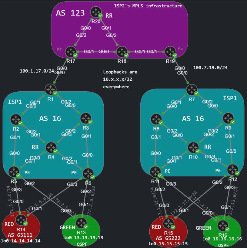
Basically we need another service provider "in the middle", because let's say the two sites (right and left side) are geographically separated, and ISP1 cannot provide a single MPLS domain end-to-end. So ISP1, in this example is called the customer carrier that the customers (RED and GREEN) connect to, and ISP2 is the core carrier who provides transit connectivity for ISP1. CSC is sometimes called hierarchical L3VPN, for a reason: from the perspective of ISP2, ISP1 is a customer and it is configured in a VRF, just like in inter-AS Option A.
Implementing Carrier Supporting Carrier
First we need to establish a VPNv4 BGP neighborship between R4 and R10, the two Route Reflectors. Both have two clients: the clients of R4 are R5 and R6, and the clients of R10 are R11 and R12. This time we don't have any BGP configurations on R1 and R7 at this point.
Building VPNv4 BGP neighborship between R4 and R10
R4(config)#router bgp 16R4(config-router)#neighbor 10.10.10.10 remote-as 16R4(config-router)#neighbor 10.10.10.10 update-source lo0R4(config-router)#address-family vpnv4 unicast R4(config-router-af)#neighbor 10.10.10.10 activate R10(config)#router bgp 16R10(config-router)#neighbor 10.4.4.4 remote-as 16R10(config-router)#neighbor 10.4.4.4 update-source lo0R10(config-router)#address-family vpnv4 unicast R10(config-router-af)#neighbor 10.4.4.4 activate
The neighbor relationship won't come up at this point, because the R4 doesn't have a route to R10, and R10 doesn't have a route to R4. So the neighbor relationship remains Idle for now:
R10(config-router-af)#do show bgp vpnv4 unicast all summary | begin NeighbNeighbor V AS MsgRcvd MsgSent TblVer InQ OutQ Up/Down State/PfxRcd10.4.4.4 4 16 0 0 1 0 0 never Idle10.11.11.11 4 16 51 50 6 0 0 00:41:31 410.12.12.12 4 16 49 48 6 0 0 00:39:57 4
This will go Up of course when we learn the routes to the remote RR.
Building the IPv4 Labeled Unicast (LU) sessions between ISP1 and ISP2
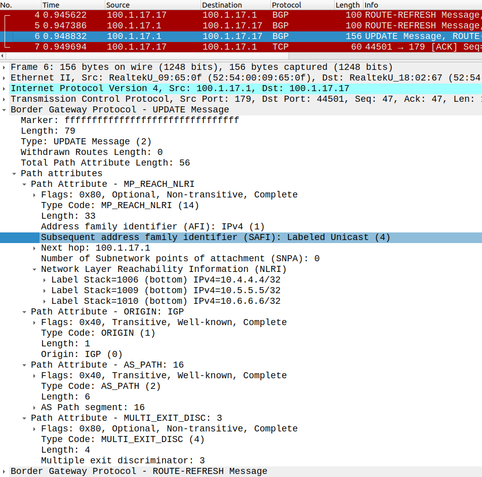
As we've seen in Option C, we build a IPv4 LU BGP neighborship between R1-R17 and R7-R19. For obvious reasons we can't just run LDP between the two service providers, but we need to maintain the transport label end-to-end, so we use BGP to exchange label information. So besides the prefix the routers also send a corresponding label to their peer:
R1(config)#router bgp 16R1(config-router)#neighbor 100.1.17.17 remote-as 123R1(config-router)#address-family ipv4 unicast R1(config-router-af)#neighbor 100.1.17.17 activate R1(config-router-af)#neighbor 100.1.17.17 send-label R7(config)#router bgp 16R7(config-router)#neighbor 100.7.19.19 remote-as 123R7(config-router)#address-family ipv4 unicast R7(config-router-af)#neighbor 100.7.19.19 activate R7(config-router-af)#neighbor 100.7.19.19 send-label
The Labeled Unicast address-family is actually configured under the IPv4 unicast AFI with the send-label command, so we need to have this on both sides for the neighbor relationship to establish.
Configure the VRF on the PEs of the core carrier and establish the IPv4 LU neighborships with ISP1
On the side of ISP2, we configure the customer facing interfaces into VRFs on the PE routers (R17 and R19). Notice that the customer here is ISP1, as I mentioned above: ISP2 treats ISP1 as a customer.
R17(config)#do show run | sec vrf defivrf definition ISP1 rd 123:1 route-target export 123:16 route-target import 123:16 ! address-family ipv4 exit-address-familyR17(config)#int g0/0R17(config-if)#vrf forwarding ISP1 % Interface GigabitEthernet0/0 IPv4 disabled and address(es) removed due to enabling VRF ISP1R17(config-if)#ip address 100.1.17.17 255.255.255.0R17(config-if)#no shut
The import/export Route Target (RT) on R17 has to match with the import/export RT of R19. This RT has nothing to do with the RT of the customer carrier (ISP1). This RT is used for a separate VPNv4 BGP session which is built within the infrastructure of ISP2. So I simply copy-paste this vrf definition to R19, and configure int g0/0 the same way as above. The VPNv4 BGP neighborship within ISP2's infrastructure is between R17 and R19, and we use R20 as a RR. Here is the BGP configuration of R20 for example:
R20#show run | sec bgprouter bgp 123 bgp log-neighbor-changes no bgp default ipv4-unicast neighbor 10.17.17.17 remote-as 123 neighbor 10.17.17.17 update-source Loopback0 neighbor 10.19.19.19 remote-as 123 neighbor 10.19.19.19 update-source Loopback0 ! address-family ipv4 exit-address-family ! address-family vpnv4 neighbor 10.17.17.17 activate neighbor 10.17.17.17 send-community extended neighbor 10.17.17.17 route-reflector-client neighbor 10.19.19.19 activate neighbor 10.19.19.19 send-community extended neighbor 10.19.19.19 route-reflector-client exit-address-family
Besides the VPNv4, we also need to run the IPv4 LU SAFI towards the CEs of ISP1 (R1 and R7, which we have already configured above). Notice that R1 and R7 are CEs from the perspective of the core carrier. Also notice that we only have a single VRF for ISP1 on the PEs of ISP2, doesn't matter how many customers ISP1 has. In this example ISP1 has two customers, but even if he had 1000, we would only configure a single VRF on the ISP2 PE. So there are no subinterfaces or separate VRFs for each customer on the PEs of ISP2, just like with Option A. This design much more scalable.
R17(config)#router bgp 123R17(config-router)#address-family ipv4 unicast vrf ISP1R17(config-router-af)#neighbor 100.1.17.1 remote-as 16R17(config-router-af)#neighbor 100.1.17.1 send-label %BGP-5-ADJCHANGE: neighbor 100.1.17.1 vpn vrf ISP1 Up %BGP_LMM-6-AUTOGEN1: The mpls bgp forwarding command has been configured on interface: GigabitEthernet0/0R19(config)#router bgp 123R19(config-router)#address-family ipv4 unicast vrf ISP1R19(config-router-af)#neighbor 100.7.19.7 remote-as 16R19(config-router-af)#neighbor 100.7.19.7 send-label %BGP-5-ADJCHANGE: neighbor 100.7.19.7 vpn vrf ISP1 Up %BGP_LMM-6-AUTOGEN1: The mpls bgp forwarding command has been configured on interface: GigabitEthernet0/0
Just as with Option B, the mpls bgp forwarding command has been automatically applied to the VRF-aware interface, so that the routers can send labelled traffic towards ISP1. So this is what we have right now regarding the BGP neighborships:
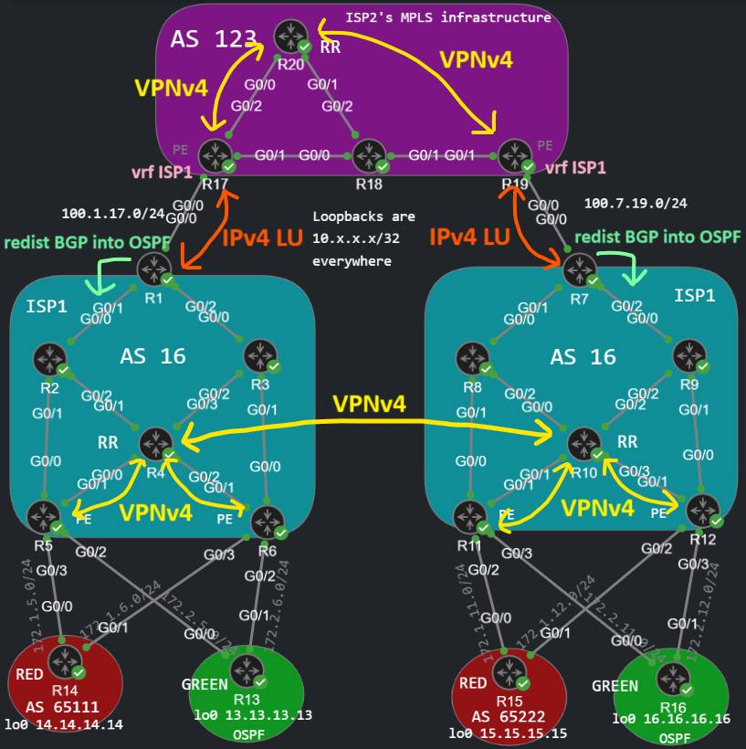
Ignore the redistribution at the edge routers of ISP1 right now, we'll get there later.
Next we advertise the address of the RRs with BGP on R1 and R7:
R1(config-router-af)#network 10.4.4.4 mask 255.255.255.255R7(config-router-af)#network 10.10.10.10 mask 255.255.255.255
They have already learned it with the IGP of course which is OSPF in this case. And let's verify that ISP2 has learned these prefixes:
R20#show bgp vpnv4 unicast all | begin Netw Network Next Hop Metric LocPrf Weight PathRoute Distinguisher: 123:1 *>i 10.4.4.4/32 10.17.17.17 3 100 0 16 i *>i 10.10.10.10/32 10.19.19.19 3 100 0 16 i
AS-Override
But R1 doesn't learn the route to the remote RR, similarly on the other side, R7 neither.
R1#show bgp ipv4 unicast | begin Netw Network Next Hop Metric LocPrf Weight Path *> 10.4.4.4/32 10.0.13.3 3 32768 i
We can make sure that R17 advertises this route:
R17#show bgp vpnv4 unicast all neighbors 100.1.17.1 advertised-routes | begin Netwo Network Next Hop Metric LocPrf Weight PathRoute Distinguisher: 123:1 (default for vrf ISP1) *>i 10.10.10.10/32 10.19.19.19 3 100 0 16 i
But the problem is the AS-Path loop prevention on R1: the AS-Path of this prefix already contains AS 16, because we use AS 16 at both locations, so R1 drops the prefix:
R1#debug ip bgp updates BGP updates debugging is on for address family: IPv4 Unicast R1#clear ip bgp * inBGP(0): 100.1.17.17 rcv UPDATE about 10.10.10.10/32 -- DENIED due to: AS-PATH contains our own AS;, label 17
There are two workarounds for this, we could either use the allowas-in on R1 and R7, or we can overwrite the AS on the PEs of ISP2, which is what we're going to do this time:
R17(config)#router bgp 123R17(config-router)#address-family ipv4 unicast vrf ISP1R17(config-router-af)#neighbor 100.1.17.1 as-override
R19(config)#router bgp 123R19(config-router)#address-family ipv4 unicast vrf ISP1R19(config-router-af)#neighbor 100.7.19.7 as-override
Now R1 and R7 accept the prefix with a modified AS-Path:
R1#show bgp ipv4 unicast | begin Net Network Next Hop Metric LocPrf Weight Path *> 10.4.4.4/32 10.0.13.3 3 32768 i *> 10.10.10.10/32 100.1.17.17 0 123 123 i
Now the AS-Path is 123 123 i, because R17 has removed R1's ASN (AS 16) and put his own AS number in that place.
Redistributing BGP into IGP on R1 and R7
We need to redistribute the prefixes learned via BGP (10.10.10.10/32 on R1 and 10.4.4.4/32 on R10) into OSPF, so that the RRs would be able to reach each other, and we could generate a label for these prefixes:
R1(config)#router ospf 1R1(config-router)#redistribute bgp 16 subnets R7(config)#router ospf 1R7(config-router)#redistribute bgp 16 subnets
And at this point the VPNv4 BGP neighborship between R4 and R10 should come up, which we configured right at the beginning of this lab, and the two RRs should be able to exchange routes with each other:
R4#show bgp vpnv4 uni all summ | begin NeighNeighbor V AS MsgRcvd MsgSent TblVer InQ OutQ Up/Down State/PfxRcd10.5.5.5 4 16 108 115 6 0 0 01:35:29 410.6.6.6 4 16 110 112 6 0 0 01:35:19 410.10.10.10 4 16 8 9 6 0 0 00:00:52 4
Next-Hop issues
Now the RRs can learn the prefixes of the remote sites, but they cannot forward them because they can't reach the next hop addresses which point to the remote PE routers, R11 and R12 in this case:
R4#show bgp vpnv4 uni all | begin Netw Network Next Hop Metric LocPrf Weight PathRoute Distinguisher: 16:1 * i 14.14.14.14/32 10.6.6.6 0 100 0 65111 i *>i 10.5.5.5 0 100 0 65111 iRoute Distinguisher: 16:2 *>i 13.13.13.13/32 10.5.5.5 2 100 0 ? * i 10.6.6.6 2 100 0 ? * i 172.2.5.0/24 10.6.6.6 2 100 0 ? *>i 10.5.5.5 0 100 0 ? * i 172.2.6.0/24 10.5.5.5 2 100 0 ? *>i 10.6.6.6 0 100 0 ?Route Distinguisher: 16:11 * i 15.15.15.15/32 10.11.11.11 0 100 0 65222 iRoute Distinguisher: 16:22 * i 16.16.16.16/32 10.11.11.11 2 100 0 ? * i 172.2.11.0/24 10.11.11.11 0 100 0 ? * i 172.2.12.0/24 10.12.12.12 0 100 0 ?
So we also need to advertise the loopback of all PEs with BGP: the loopback of R5 and R6 on R1, and we advertise the loopback of R11 and R12 on R7:
R1(config-router-af)#network 10.5.5.5 mask 255.255.255.255R1(config-router-af)#network 10.6.6.6 mask 255.255.255.255R7(config-router-af)#network 10.11.11.11 mask 255.255.255.255R7(config-router-af)#network 10.12.12.12 mask 255.255.255.255
And now all routes should be both valid and best, and the RRs can forward them to their PE clients:
R4#show bgp vpnv4 uni all | begin Netw Network Next Hop Metric LocPrf Weight PathRoute Distinguisher: 16:1 * i 14.14.14.14/32 10.6.6.6 0 100 0 65111 i *>i 10.5.5.5 0 100 0 65111 iRoute Distinguisher: 16:2 *>i 13.13.13.13/32 10.5.5.5 2 100 0 ? * i 10.6.6.6 2 100 0 ? * i 172.2.5.0/24 10.6.6.6 2 100 0 ? *>i 10.5.5.5 0 100 0 ? * i 172.2.6.0/24 10.5.5.5 2 100 0 ? *>i 10.6.6.6 0 100 0 ?Route Distinguisher: 16:11 *>i 15.15.15.15/32 10.11.11.11 0 100 0 65222 iRoute Distinguisher: 16:22 *>i 16.16.16.16/32 10.11.11.11 2 100 0 ? *>i 172.2.11.0/24 10.11.11.11 0 100 0 ? *>i 172.2.12.0/24 10.12.12.12 0 100 0 ?
And now the customers can reach their remote sites. Notice that ISP2 and AS 123 is totally transparent for the customers:
R14#show ip bgp | begin Netwo Network Next Hop Metric LocPrf Weight Path *> 14.14.14.14/32 0.0.0.0 0 32768 i * 15.15.15.15/32 172.1.6.6 0 16 65222 i *> 172.1.5.5 0 16 65222 i
Also customer GREEN who runs OSPF as the PE-CE protocol has the routes of his remote site:
R16#show ip route ospf | begin GateGateway of last resort is not set 13.0.0.0/32 is subnetted, 1 subnetsO IA 13.13.13.13 [110/3] via 172.2.12.12, 00:05:07, GigabitEthernet0/1 [110/3] via 172.2.11.11, 00:05:07, GigabitEthernet0/0 172.2.0.0/16 is variably subnetted, 6 subnets, 2 masksO IA 172.2.5.0/24 [110/2] via 172.2.12.12, 00:05:07, GigabitEthernet0/1 [110/2] via 172.2.11.11, 00:05:07, GigabitEthernet0/0O IA 172.2.6.0/24 [110/2] via 172.2.12.12, 00:04:37, GigabitEthernet0/1 [110/2] via 172.2.11.11, 00:04:37, GigabitEthernet0/0
And finally let's take a look at the MPLS label stack when R14 sends a packet to R15:
R14#traceroute 15.15.15.15 source lo0 numeric Type escape sequence to abort.Tracing the route to 15.15.15.15VRF info: (vrf in name/id, vrf out name/id) 1 172.1.5.5 2 msec 1 msec 2 msec 2 10.0.25.2 [MPLS: Labels 2011/11014 Exp 0] 9 msec 9 msec 5 msec 3 10.0.12.1 [MPLS: Labels 1013/11014 Exp 0] 8 msec 10 msec 9 msec 4 100.1.17.17 [MPLS: Labels 1708/11014 Exp 0] 9 msec 11 msec 9 msec 5 10.17.18.18 [MPLS: Labels 1802/1909/11014 Exp 0] 10 msec 10 msec 8 msec 6 100.7.19.19 [MPLS: Labels 1909/11014 Exp 0] 8 msec 10 msec 10 msec 7 100.7.19.7 [MPLS: Labels 7006/11014 Exp 0] 9 msec 8 msec 9 msec 8 10.7.8.8 [MPLS: Labels 8005/11014 Exp 0] 9 msec 8 msec 9 msec 9 172.1.11.11 [MPLS: Label 11014 Exp 0] 8 msec 8 msec 8 msec 10 172.1.11.15 8 msec * 7 msec
As we can see, we have three labels within ISP2's infrastructure, specifically between R17 and R18:
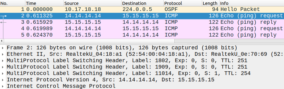
R18 then does the PHP and removes the topmost label. The inner VPN label (11014 in this case) remains the same end-to-end which R11 has generated for this route. The routers within the infrastructure of ISP1 swap the transport label, including R1 who swaps the topmost transport label when he sends the packet towards ISP2, that's why we need the IPv4 LU BGP to send the labels between the service providers. Within the infrastructure of the core carrier we also have a VPN label (1909 in this case) which identifies ISP1 as a customer and which R19 generated and sent to R17 via VPNv4 BGP. When R19 sends the packet to ISP1, he then removes this VPN label which is only significant within ISP2's infrastructure, and R19 sends the packet with a transport label towards R7. Now at this point we have two labels, the routers swap the transport label, just like with intra-AS L3VPN.