Configuring E-LAN (VPLS) service over the MPLS cloud using CSR1000v routers
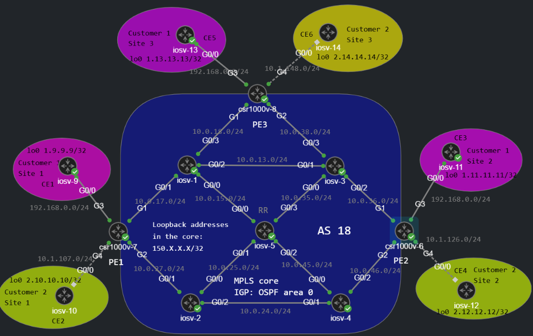
I'm going to build a L2VPN service for Customer 1 sites (purple), and create an "emulated" switching environment within the MPLS core: CE1, CE3, and CE5 routers are going to be placed in the same broadcast domain, the MPLS core will be completely transparent for Customer 1. The whole MPLS core will behave like a huge switch: it learns MAC addresses on the ports of the PE routers, and floods BUM (broadcast/unknown unicast/multicast) traffic to all remote PEs.
Note: L2 VPN services are not supported on regular IOSv images, so I'll be using IOS-XE with the CSR1000v images, they will be the PEs in this topology (PE1-2-3). Just ignore the Customer 2 sites, the Route Reflector and everything related to iBGP in this lab, they're used for L3VPN services. For L2VPN we'll only need LDP as the control plane within the MPLS core. So let's begin!
First let's enable MPLS globally under the OSPF process and establish the LDP neighborships within the core. I also create a custom label range for each router in the core for troubleshooting purposes, like this:
R6_PE2(config)#mpls label range 600 699R6_PE2(config-router)#mpls ldp autoconfig R7_PE2(config)#mpls label range 700 799R7_PE2(config-router)#mpls ldp autoconfig R8_PE3(config)#mpls label range 800 899R8_PE3(config-router)#mpls ldp autoconfig Next, we create a service instance on the customer facing interfaces, for PE2 that's G3 for example:
R6_PE2(config)#interface g3R6_PE2(config-if)#no ip address R6_PE2(config-if)#no shutdown R6_PE2(config-if)#service instance 100 ethernet R6_PE2(config-if-srv)#encapsulation default R6_PE2(config-if-srv)#bridge-domain 678The service instance number is locally significant here (doesn't have to match with the other PEs), but the bridge domain has to match. We also create the bridge domain globally to be able to learn the MAC addresses, and forward frames based on MAC addresses like a real switch does (in some cases this is not necessary, it'll be automatically created):
R6_PE2(config)#bridge-domain 678R6_PE2(config-bdomain)#Next we create the l2 vfi (Virtual Forwarding Instance) like this:
R6_PE2(config)#l2 vfi VPLS manual R6_PE2(config-vfi)#vpn id 123R6_PE2(config-vfi)#bridge-domain 678R6_PE2(config-vfi)#neighbor 150.7.7.7 encapsulation mpls R6_PE2(config-vfi)#neighbor 150.8.8.8 encapsulation mpls Here the vpn id and the bridge domain has to match with all other PEs. And we need an individual neighbor statement for all other PEs: here we have 3 sites so we need 2 neighbor statement for PE1 (150.7.7.7) and PE3 (150.8.8.8) in this case. [These addresses should already be present in the RIB and learned via OSPF]. So just like with iBGP, we need a full-mesh configuration, if you have a lot of PEs this soulution is obviously not going to scalabe, in that case you'll need BGP. But otherwise we need a targeted LDP session with every other PE router.
The moment we configure the individual neighbor statements a targeted LDP Hello (Discovery) is sent to the remote PE, and a targeted LDP session is established between the loopbacks:
R7_PE2(config-vfi)# neighbor 150.6.6.6 encapsulation mpls R7_PE2(config-vfi)#*Jun 17 11:03:06.202: %LDP-5-NBRCHG: LDP Neighbor 150.6.6.6:0 (2) is UPSo we use LDP as the control plane, here is an example of an LDP Label Mapping message:
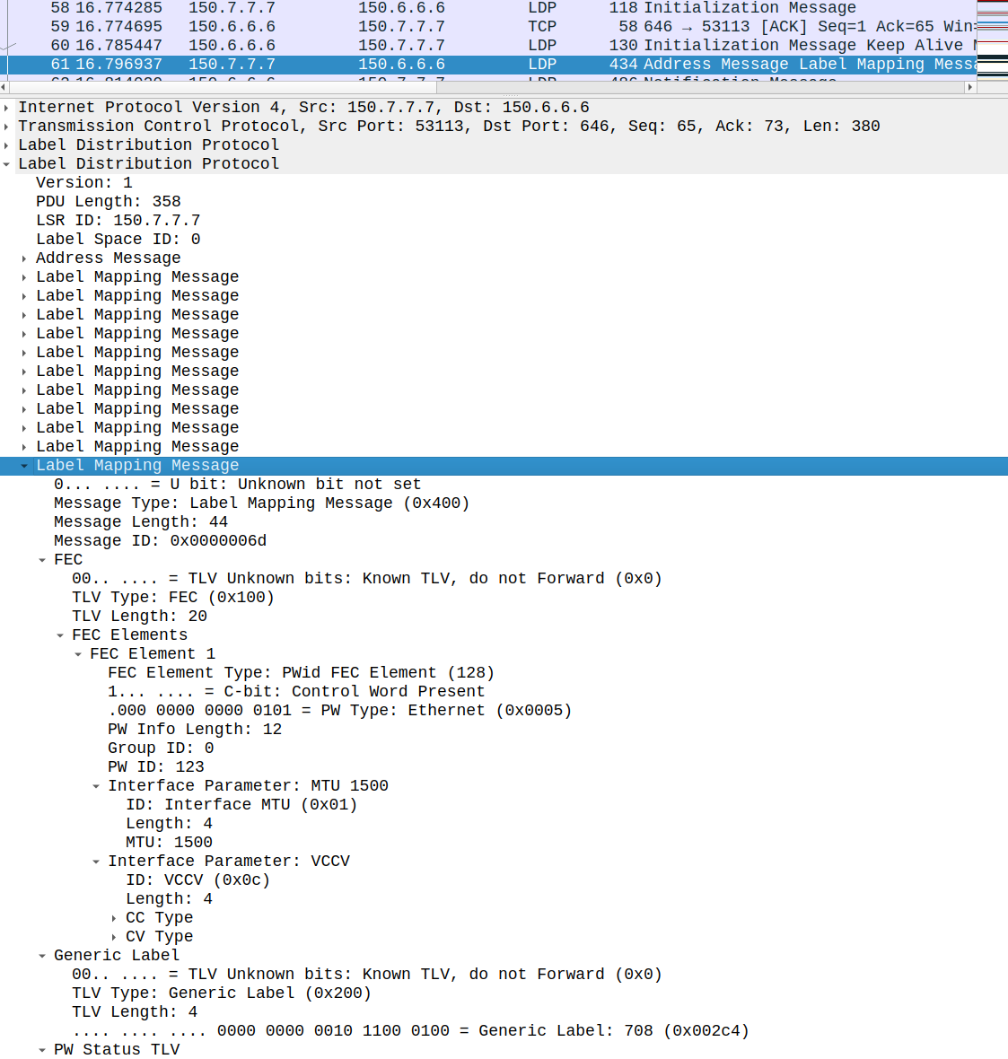
Here you can see VPN label (inner label) information for PE1 (708), the MTU for VPLS instance (1500 bytes, more on this later), and the PW ID (123, which is the vpn id under the l2 vfi) which has to match with the other PEs.
Next let's configure CE routers: they have to be in the same subnet (in this example 192.168.0.0/24, we use the router number in the last octet). I also enable OSPF on the MPLS core facing interfaces to demonstate that they'll be establishing adjacency with each other:
interface GigabitEthernet0/0 ip address 192.168.0.9 255.255.255.0 ip ospf 1 area 0R9_CE1(config-if)#do show ip ospf neighbor Neighbor ID Pri State Dead Time Address Interface1.11.11.11 1 FULL/DROTHER 00:00:36 192.168.0.11 GigabitEthernet0/01.13.13.13 1 FULL/DR 00:00:32 192.168.0.13 GigabitEthernet0/0We have a DR, BDR and DROTHER in the subnet, and they've established neighbor relationship with each other, since they are in an emulated broadcast domain.
From CE3's perspective CE1 is a single hop:
R11_CE3#traceroute 1.9.9.9 so lo0 numeric Type escape sequence to abort.Tracing the route to 1.9.9.9VRF info: (vrf in name/id, vrf out name/id) 1 192.168.0.9 4 msec * 2 msecFor verification we can use the following:
R6_PE2#show vfi Legend: RT=Route-target, S=Split-horizon, Y=Yes, N=NoVFI name: VPLS, state: up, type: multipoint, signaling: LDP VPN ID: 123 Bridge-Domain 678 attachment circuits: Neighbors connected via pseudowires: Peer Address VC ID S 150.8.8.8 123 Y 150.7.7.7 123 YR6_PE2#show mpls ldp neighbor Peer LDP Ident: 150.3.3.3:0; Local LDP Ident 150.6.6.6:0 TCP connection: 150.3.3.3.646 - 150.6.6.6.14778 State: Oper; Msgs sent/rcvd: 21/23; Downstream Up time: 00:07:24 LDP discovery sources: GigabitEthernet1, Src IP addr: 10.0.36.3 Addresses bound to peer LDP Ident: 10.0.35.3 10.0.13.3 10.0.36.3 10.0.38.3 150.3.3.3 Peer LDP Ident: 150.7.7.7:0; Local LDP Ident 150.6.6.6:0 TCP connection: 150.7.7.7.53113 - 150.6.6.6.646 State: Oper; Msgs sent/rcvd: 23/23; Downstream Up time: 00:07:24 LDP discovery sources: Targeted Hello 150.6.6.6 -> 150.7.7.7, active, passive Addresses bound to peer LDP Ident: 10.0.17.7 10.0.27.7 150.7.7.7 Peer LDP Ident: 150.8.8.8:0; Local LDP Ident 150.6.6.6:0 TCP connection: 150.8.8.8.25069 - 150.6.6.6.646 State: Oper; Msgs sent/rcvd: 23/23; Downstream Up time: 00:07:24 LDP discovery sources: Targeted Hello 150.6.6.6 -> 150.8.8.8, active, passive Addresses bound to peer LDP Ident: 10.0.18.8 10.0.38.8 150.8.8.8 Use this for the control plane, targeted LDP sessions must be established between the PEs; make sure the loopbacks are advertised with your IGP in the core. For data plane use this:
R6_PE2#show bridge-domain Bridge-domain 678 (3 ports in all)State: UP Mac learning: EnabledAging-Timer: 300 second(s)Maximum address limit: 65536 GigabitEthernet3 service instance 100 vfi VPLS neighbor 150.7.7.7 123 vfi VPLS neighbor 150.8.8.8 123 AED MAC address Policy Tag Age Pseudoport 0 5254.0018.1618 forward dynamic 296 VPLS.404012 0 5254.0002.3C01 forward dynamic 300 GigabitEthernet3.EFP100 0 5254.0019.4A14 forward dynamic 295 VPLS.404011In this example we can see the local CE and the 2 remote CEs MAC addresses, and also the MAC address aging timer decreasing (300 sec by default). Here is a packet capture between PE2 (csr1000v-6) and R3 (iosv-3):
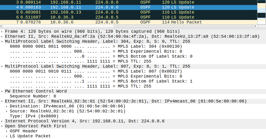
Just like with L3VPN services we have 2 labels: an inner label (VPN label) of 807 which identifies the remote PE (so this frame is destined to csr1000v-8 [PE3]), and an outer label (transport label) of 304, so this frame was sent to R3 in the MPLS core. Just like with L3VPNs R3 is going to perform PHP and remove the transport label before forwarding the frame to the remote PE. The content of the data packet is a control packet for the VPLS servicein this case: it's an OSPF Link State Update which was sent to the DR based on the destination address (224.0.0.6), so CE5 (iosv-13) must be the DR according to this LSU. So we can confirm what we have seen with the
show ip ospf neighbor command previously.