Configuring MPLS L3VPNs and VRFs in GNS3
I’ve been learning to configure MPLS and VRFs recently. I’m using GNS3 network emulator with real Cisco IOS images since other simulators such as Packet Tracer doesn’t support MPLS and VRF configuration. Running MPLS and having VRFs have many advantages: without using MPLS the customer routers could see the core network, and they could access any core routers. With using MPLS the customers are unaware of the core network and the provider (P) routers. Defining VRFs solves the problem of overlapping networks: by defining different VRFs we can assign the same IP address to different interfaces, since we will have them in different routing tables, and they are separated from the global routing table.
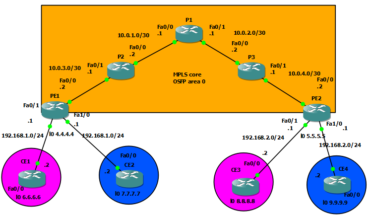
In the topology below I’m going to enable MPLS in the core network, configure BGP on the edge routers, create two VRFs with the same IP address, and redistribute routes on the edge routers. By doing so the customers at both edge routers in the same VRFs will be able to ping each other. Lastly I’m going to hide the MPLS network from the customers.
1) Configuring the MPLS core
At first I created loopback addresses, assigned IP addresses to each interface and enabled OSPF for the core routers. This is pretty much straightforward, here are the commands I have issued on P1:
P1#configure terminal
Enter configuration commands, one per line.  End with CNTL/Z.
P1(config)#interface loopback0
P1(config-if)#ip addre
*Mar  1 00:01:26.251: %LINEPROTO-5-UPDOWN: Line protocol on Interface Loopback0, changed state to up
P1(config-if)#ip address 1.1.1.1 255.255.255.255
P1(config-if)#ip ospf 1 area 0
P1(config-if)#interface Fa0/0
P1(config-if)#ip address 10.0.1.1 255.255.255.252
P1(config-if)#ip ospf 1 area 0
P1(config-if)#no shutdown
P1(config-if)#
*Mar  1 00:02:31.547: %LINK-3-UPDOWN: Interface FastEthernet0/0, changed state to up
*Mar  1 00:02:32.547: %LINEPROTO-5-UPDOWN: Line protocol on Interface FastEthernet0/0, changed state to up
P1(config-if)#interface Fa0/1
P1(config-if)#ip address 10.0.2.1 255.255.255.252
P1(config-if)#ip ospf 1 area 0
P1(config-if)#no shutdown
P1(config-if)#
*Mar  1 00:03:45.651: %LINK-3-UPDOWN: Interface FastEthernet0/1, changed state to up
*Mar  1 00:03:46.651: %LINEPROTO-5-UPDOWN: Line protocol on Interface FastEthernet0/1, changed state to up
P1(config-if)#
*Mar  1 00:05:12.803: %OSPF-5-ADJCHG: Process 1, Nbr 2.2.2.2 on FastEthernet0/0 from LOADING to FULL, Loading Done
P1(config-if)#
*Mar  1 00:08:11.611: %OSPF-5-ADJCHG: Process 1, Nbr 3.3.3.3 on FastEthernet0/1 from LOADING to FULL, Loading Done
Of course we don’t want to enable MPLS on the interfaces of PE routers facing to the customers. We only want to enable MPLS on the Fa0/0 interfaces which are part of the core network. Besides that we’re going to need to run different OSPF processes on each customer interface, so for now I didn’t do any configuration on them, I just left them shutdown, here are the commands on PE2:
PE2#configure terminal
Enter configuration commands, one per line.  End with CNTL/Z.
PE2(config)#interface loopback 0
PE2(config-if)#
*Mar  1 00:07:41.215: %LINEPROTO-5-UPDOWN: Line protocol on Interface Loopback0, changed state to up
PE2(config-if)#ip address 5.5.5.5 255.255.255.255
PE2(config-if)#ip ospf 1 area 0
PE2(config-if)#interface Fa0/0
PE2(config-if)#ip address 10.0.4.2 255.255.255.252
PE2(config-if)#ip ospf 1 area 0
PE2(config-if)#no shutdown
PE2(config-if)#
*Mar  1 00:08:35.883: %OSPF-5-ADJCHG: Process 1, Nbr 3.3.3.3 on FastEthernet0/0 from LOADING to FULL, Loading Done
PE2(config-if)#
*Mar  1 00:08:36.423: %LINK-3-UPDOWN: Interface FastEthernet0/0, changed state to up
*Mar  1 00:08:37.423: %LINEPROTO-5-UPDOWN: Line protocol on Interface FastEthernet0/0, changed state to up
Next I configured MPLS on each interface in the core network after specifying label distribution protocol. Configuring MPLS in the core is really easy, you can see the LDP neighbor relationship messages popping up after the configuration of neighbor interfaces. I could have used the mpls ldp autoconfig command as well after specifying the OSPF process 1. Finally I have issued some show commands to verify that MPLS works properly. From now on labels are used to switch traffic between interfaces in the core network, but labels are not going to be used in the links to the customer networks. To accomplish that PE routers insert and remove the labels.
P1(config)#
P1(config)#mpls ip
P1(config)#mpls label protocol ldp
P1(config)#interface Fa0/0
P1(config-if)#mpls ip
P1(config-if)#interface Fa0/1
P1(config-if)#mpls ip
P1(config-if)#
*Mar  1 00:18:09.199: %LDP-5-NBRCHG: LDP Neighbor 2.2.2.2:0 (1) is UP
P1(config-if)#
*Mar  1 00:19:37.335: %LDP-5-NBRCHG: LDP Neighbor 3.3.3.3:0 (2) is UP
P1(config-if)#exit
P1(config)#do show mpls interface
Interface              IP            Tunnel   Operational
FastEthernet0/0        Yes (ldp)     No       Yes
FastEthernet0/1        Yes (ldp)     No       Yes
P1(config)#do show mpls ldp neighbor
    Peer LDP Ident: 2.2.2.2:0; Local LDP Ident 1.1.1.1:0
        TCP connection: 2.2.2.2.37490 - 1.1.1.1.646
        State: Oper; Msgs sent/rcvd: 17/17; Downstream
        Up time: 00:04:51
        LDP discovery sources:
          FastEthernet0/0, Src IP addr: 10.0.1.2
        Addresses bound to peer LDP Ident:
          10.0.1.2        10.0.3.1        2.2.2.2
    Peer LDP Ident: 3.3.3.3:0; Local LDP Ident 1.1.1.1:0
        TCP connection: 3.3.3.3.11159 - 1.1.1.1.646
        State: Oper; Msgs sent/rcvd: 15/15; Downstream
        Up time: 00:03:23
        LDP discovery sources:
          FastEthernet0/1, Src IP addr: 10.0.2.2
        Addresses bound to peer LDP Ident:
          10.0.2.2        10.0.4.1        3.3.3.3
I have run a traceroute from PE1 to PE2 (5.5.5.5), you can see the labels which are used across the different links to PE2. In this case P3 removes the label and forwards the traffic as IP traffic to PE2:
PE1#traceroute 5.5.5.5

Type escape sequence to abort.
Tracing the route to 5.5.5.5

  1 10.0.3.1 [MPLS: Label 19 Exp 0] 60 msec 40 msec 44 msec
  2 10.0.1.1 [MPLS: Label 19 Exp 0] 36 msec 80 msec 28 msec
  3 10.0.2.2 [MPLS: Label 19 Exp 0] 68 msec 40 msec 28 msec
  4 10.0.4.2 40 msec 60 msec 24 msec
2) Configuring BGP on PE routers
In the next step we are going to configure BGP. BGP is only going to be used between PE routers., the provider routers are only running OSPF. By configuring BGP we specify the loopback address of the other PE router as neighbor, we create an address-family, and activate the neighbor. With the show command we can verify that BGP works properly between the PE routers.
PE1(config)#router bgp 100
PE1(config-router)#neighbor 5.5.5.5 remote-as 100
PE1(config-router)#neighbor 5.5.5.5 update-source loopback0
PE1(config-router)#no auto-summary
PE1(config-router)#address-family vpnv4
PE1(config-router-af)#neighbor 5.5.5.5 activate
PE1(config-router-af)#neighbor 5.5.5.5 send-community extended
PE1(config-router-af)#
*Mar  1 00:22:38.471: %BGP-5-ADJCHANGE: neighbor 5.5.5.5 Up
PE1(config-router-af)#
*Mar  1 00:23:10.083: %BGP-5-ADJCHANGE: neighbor 5.5.5.5 Down Peer closed the session
PE1(config-router-af)#
*Mar  1 00:23:16.215: %BGP-5-ADJCHANGE: neighbor 5.5.5.5 Up

PE2(config)#router bgp 100
PE2(config-router)#neighbor 4.4.4.4 remote-as 100
PE2(config-router)#neighbor 4.4.4.4 update-source loopback0
PE2(config-router)#no auto-summary
PE2(config-router)#a
*Mar  1 00:21:48.011: %BGP-5-ADJCHANGE: neighbor 4.4.4.4 Up
PE2(config-router)#address-family vpnv4
PE2(config-router-af)#neighbor 4.4.4.4 activate
PE2(config-router-af)#nei
*Mar  1 00:22:18.591: %BGP-5-ADJCHANGE: neighbor 4.4.4.4 Down Address family activated
*Mar  1 00:22:25.703: %BGP-5-ADJCHANGE: neighbor 4.4.4.4 Up
PE2(config-router-af)#neighbor 4.4.4.4 send-community extended
PE2(config-router-af)#

PE1#show bgp vpnv4 unicast all summary
BGP router identifier 4.4.4.4, local AS number 100
BGP table version is 1, main routing table version 1

Neighbor        V    AS MsgRcvd MsgSent   TblVer  InQ OutQ Up/Down  State/PfxRcd
5.5.5.5         4   100       9       9        1    0    0 00:02:57        0
3) Configuring CE routers
Configuring the CE routers is very straightforward: I created a loopback interface, assigned an IP address for the Fa0/0 interface and enabled OSPF. The configuration on the other side, on the CE3 and CE4 routers is very similar, I’m going to omit the commands of those routers.
CE1#configure terminal
Enter configuration commands, one per line.  End with CNTL/Z.
CE1(config)#interface loopback 0
CE1(config-if)#ip addre
*Mar  1 00:18:08.963: %LINEPROTO-5-UPDOWN: Line protocol on Interface Loopback0, changed state to up
CE1(config-if)#ip address 6.6.6.6 255.255.255.255
CE1(config-if)#ip ospf 1 area 0
CE1(config-if)#interface Fa0/0
CE1(config-if)#ip address 192.168.1.2 255.255.255.0
CE1(config-if)#ip ospf 1 area 0
CE1(config-if)#no shutdown
CE1(config-if)#
*Mar  1 00:19:04.723: %LINK-3-UPDOWN: Interface FastEthernet0/0, changed state to up
*Mar  1 00:19:05.723: %LINEPROTO-5-UPDOWN: Line protocol on Interface FastEthernet0/0, changed state to up
CE1(config-if)#
*Mar  1 00:20:19.827: %OSPF-5-ADJCHG: Process 1, Nbr 192.168.1.1 on FastEthernet0/0 from LOADING to FULL, Loading Done

CE2#configure terminal
Enter configuration commands, one per line.  End with CNTL/Z.
CE2(config)#interface loopback0
CE2(config-if)#
*Mar  1 00:20:12.619: %LINEPROTO-5-UPDOWN: Line protocol on Interface Loopback0, changed state to up
CE2(config-if)#ip address 7.7.7.7 255.255.255.255
CE2(config-if)#ip ospf 1 area 0
CE2(config-if)#interface Fa0/0
CE2(config-if)#ip address 192.168.1.2 255.255.255.0
CE2(config-if)#ip ospf 1 area 0
CE2(config-if)#no shutdown
CE2(config-if)#
*Mar  1 00:21:40.283: %LINK-3-UPDOWN: Interface FastEthernet0/0, changed state to up
*Mar  1 00:21:41.283: %LINEPROTO-5-UPDOWN: Line protocol on Interface FastEthernet0/0, changed state to up
CE2(config-if)#
*Mar  1 00:26:12.119: %OSPF-5-ADJCHG: Process 1, Nbr 192.168.1.100 on FastEthernet0/0 from LOADING to FULL, Loading Done
4) Creating VRFs for customers
We are going to put the interfaces of PE routers to customers into different VRFs and assign the same IP address to prove they can have the same. To differentiate the routes which are advertised with BGP we need to have a route distinguisher. Usually the first number is the number of the autonomous system, and with the other number we distinguish the customers. We need to configure routing protocol for the customers, in this case OSPF, but we need a different process number: for the core network we used process 1, for the VRFs we are going to use process 2 and 3. Of course it cannot use the IP address of the loopback 0 interface as router-id, so need to specify a new router-id eventually. In this case after turning the interface on its IP address was used as router-id.
PE1(config)#ip vrf PURPLE
PE1(config-vrf)#rd 100:1
PE1(config-vrf)#route-target both 100:1
PE1(config-vrf)#exit
PE1(config)#interface Fa0/1
PE1(config-if)#ip address 192.168.1.1 255.255.255.0
PE1(config-if)#ip vrf forwarding PURPLE
% Interface FastEthernet0/1 IP address 192.168.1.1 removed due to enabling VRF PURPLE
PE1(config-if)#ip address 192.168.1.1 255.255.255.0
PE1(config-if)#ip ospf 2 area 0
PE1(config-if)#
*Mar  1 00:31:40.131: %OSPF-4-NORTRID: OSPF process 2 failed to allocate unique router-id and cannot start
PE1(config-if)#no shutdown
PE1(config-if)#
*Mar  1 00:31:52.671: %LINK-3-UPDOWN: Interface FastEthernet0/1, changed state to up
*Mar  1 00:31:53.671: %LINEPROTO-5-UPDOWN: Line protocol on Interface FastEthernet0/1, changed state to up
PE1(config-if)#ip ospf 2 area 0
PE1(config-if)#
*Mar  1 00:32:00.147: %OSPF-5-ADJCHG: Process 2, Nbr 6.6.6.6 on FastEthernet0/1 from LOADING to FULL, Loading Done
Instead of the route-target both command I could have specified route-target export 100:1 and route-target import 100:1 commands, but because in this example they are the same it’s much more simple to use a single command for both. If we had assigned an IP address to the interface previously, it would have been removed, and we would need to reassign it again, because it was part of the global routing table. Now this interface belongs to a separate routing table.
We need to configure a different route distinguisher for VRF BLUE:
PE1(config)#ip vrf BLUE
PE1(config-vrf)#rd 100:1
% RD 100:1 already in use by VRF PURPLE
PE1(config-vrf)#rd 100:2
PE1(config-vrf)#route-target both 100:2
PE1(config-vrf)#exit
PE1(config)#interface Fa1/0
PE1(config-if)#ip vrf forwarding BLUE
PE1(config-if)#ip address 192.168.1.1 255.255.255.0
PE1(config-if)#no shutdown
PE1(config-if)#ip ospf 3
*Mar  1 00:39:20.407: %LINK-3-UPDOWN: Interface FastEthernet1/0, changed state to up
*Mar  1 00:39:21.407: %LINEPROTO-5-UPDOWN: Line protocol on Interface FastEthernet1/0, changed state to up
PE1(config-if)#ip ospf 3 area 0
PE1(config-if)#
*Mar  1 00:39:25.835: %OSPF-4-NORTRID: OSPF process 3 failed to allocate unique router-id and cannot start
PE1(config-if)#exit
PE1(config)#router ospf 3
PE1(config-router)#router-id ?
  A.B.C.D  OSPF router-id in IP address format

PE1(config-router)#router-id 192.168.1.100
PE1(config-router)#exit
*Mar  1 00:40:11.299: %OSPF-5-ADJCHG: Process 3, Nbr 7.7.7.7 on FastEthernet1/0 from LOADING to FULL, Loading Done
Now we see the routing tables of the VRFs by typing the following commands:
PE1#show ip route vrf PURPLE

Routing Table: PURPLE
Codes: C - connected, S - static, R - RIP, M - mobile, B - BGP
       D - EIGRP, EX - EIGRP external, O - OSPF, IA - OSPF inter area
       N1 - OSPF NSSA external type 1, N2 - OSPF NSSA external type 2
       E1 - OSPF external type 1, E2 - OSPF external type 2
       i - IS-IS, su - IS-IS summary, L1 - IS-IS level-1, L2 - IS-IS level-2
       ia - IS-IS inter area, * - candidate default, U - per-user static route
       o - ODR, P - periodic downloaded static route

Gateway of last resort is not set

     6.0.0.0/32 is subnetted, 1 subnets
O       6.6.6.6 [110/2] via 192.168.1.2, 00:10:01, FastEthernet0/1
C    192.168.1.0/24 is directly connected, FastEthernet0/1
PE1#show ip route vrf BLUE

Routing Table: BLUE
Codes: C - connected, S - static, R - RIP, M - mobile, B - BGP
       D - EIGRP, EX - EIGRP external, O - OSPF, IA - OSPF inter area
       N1 - OSPF NSSA external type 1, N2 - OSPF NSSA external type 2
       E1 - OSPF external type 1, E2 - OSPF external type 2
       i - IS-IS, su - IS-IS summary, L1 - IS-IS level-1, L2 - IS-IS level-2
       ia - IS-IS inter area, * - candidate default, U - per-user static route
       o - ODR, P - periodic downloaded static route

Gateway of last resort is not set

     7.0.0.0/32 is subnetted, 1 subnets
O       7.7.7.7 [110/2] via 192.168.1.2, 00:02:04, FastEthernet1/0
C    192.168.1.0/24 is directly connected, FastEthernet1/0
Configuring PE2 is very similar:
PE2(config)#ip vrf PURPLE
PE2(config-vrf)#rd 100:1
PE2(config-vrf)#route-target both 100:1
PE2(config-vrf)#exit
PE2(config)#interface Fa0/1
PE2(config-if)#ip vrf forwarding PURPLE
PE2(config-if)#ip address 192.168.2.1 255.255.255.0
PE2(config-if)#ip ospf 2 area 0
PE2(config-if)#
*Mar  1 00:50:01.947: %OSPF-4-NORTRID: OSPF process 2 failed to allocate unique router-id and cannot start
PE2(config-if)#no shutdown
PE2(config-if)#ip ospf 2 area 0
*Mar  1 00:50:13.151: %LINK-3-UPDOWN: Interface FastEthernet0/1, changed state to up
PE2(config-if)#ip ospf 2 area 0
*Mar  1 00:50:13.555: %OSPF-5-ADJCHG: Process 2, Nbr 8.8.8.8 on FastEthernet0/1 from LOADING to FULL, Loading Done
*Mar  1 00:50:14.151: %LINEPROTO-5-UPDOWN: Line protocol on Interface FastEthernet0/1, changed state to up
 PE2(config-if)#
PE2(config-if)#exit
PE2(config)#ip vrf BLUE
PE2(config-vrf)#rd 100:2
PE2(config-vrf)#route-target both 100:2
PE2(config-vrf)#exit
PE2(config)#interface Fa1/0
PE2(config-if)#ip vrf forwarding BLUE
% Interface FastEthernet1/0 IP address 192.168.2.1 removed due to enabling VRF BLUE
PE2(config-if)#
*Mar  1 01:13:04.175: %OSPF-5-ADJCHG: Process 3, Nbr 9.9.9.9 on FastEthernet1/0 from FULL to DOWN, Neighbor Down: Interface down or detached
*Mar  1 01:13:04.307: %OSPF-6-PROC_REM_FROM_INT: OSPF process 3 removed from interface FastEthernet1/0
PE2(config-if)#ip address 192.168.2.1 255.255.255.0
PE2(config-if)#ip ospf 3 area 0
PE2(config-if)#
*Mar  1 01:15:16.339: %OSPF-4-NORTRID: OSPF process 3 failed to allocate unique router-id and cannot start
PE2(config-if)#exit
PE2(config)#router ospf 3
PE2(config-router)#router-id 192.168.2.200
PE2(config-router)#
*Mar  1 01:15:56.051: %OSPF-5-ADJCHG: Process 3, Nbr 9.9.9.9 on FastEthernet1/0 from LOADING to FULL, Loading Done
5) Redistribute routes
The CE routers are still not learning routes from the PE routers, so in the next part we need to redistribute routes on the edge routers. We’re going to redistribute OSPF into BGP, and redistribute BGP into OSPF to allow CE routers to learn routes from the one side of the network to the other. I’ve only inserted the configuration of PE2, the commands on PE1 are the same.
PE2(config)#router bgp 100
PE2(config-router)#address-family ipv4 vrf PURPLE
PE2(config-router-af)#redistribute ospf 2
PE2(config-router-af)#redistribute connected
PE2(config-router-af)#exit
PE2(config-router)#address-family ipv4 vrf BLUE
PE2(config-router-af)#redistribute ospf 3
PE2(config-router-af)#redistribute connected
PE2(config-router-af)#exit
PE2(config-router)#exit
PE2(config)#router ospf 2
PE2(config-router)#redistribute bgp 100 subnets
PE2(config-router)#exit
PE2(config)#router ospf 3
PE2(config-router)#redistribute bgp 100 subnets
Now we can see inter-area routes in the routing tables of the CE routers, now CEs in the same VRF can ping each other. To confirm I’ve issued the show ip route command:
CE1#show ip route
Codes: C - connected, S - static, R - RIP, M - mobile, B - BGP
       D - EIGRP, EX - EIGRP external, O - OSPF, IA - OSPF inter area
       N1 - OSPF NSSA external type 1, N2 - OSPF NSSA external type 2
       E1 - OSPF external type 1, E2 - OSPF external type 2
       i - IS-IS, su - IS-IS summary, L1 - IS-IS level-1, L2 - IS-IS level-2
       ia - IS-IS inter area, * - candidate default, U - per-user static route
       o - ODR, P - periodic downloaded static route

Gateway of last resort is not set

     6.0.0.0/32 is subnetted, 1 subnets
C       6.6.6.6 is directly connected, Loopback0
     8.0.0.0/32 is subnetted, 1 subnets
O IA    8.8.8.8 [110/3] via 192.168.1.1, 00:01:25, FastEthernet0/0
C    192.168.1.0/24 is directly connected, FastEthernet0/0
O IA 192.168.2.0/24 [110/2] via 192.168.1.1, 00:01:25, FastEthernet0/0

CE2#show ip route
Codes: C - connected, S - static, R - RIP, M - mobile, B - BGP
       D - EIGRP, EX - EIGRP external, O - OSPF, IA - OSPF inter area
       N1 - OSPF NSSA external type 1, N2 - OSPF NSSA external type 2
       E1 - OSPF external type 1, E2 - OSPF external type 2
       i - IS-IS, su - IS-IS summary, L1 - IS-IS level-1, L2 - IS-IS level-2
       ia - IS-IS inter area, * - candidate default, U - per-user static route
       o - ODR, P - periodic downloaded static route

Gateway of last resort is not set

     7.0.0.0/32 is subnetted, 1 subnets
C       7.7.7.7 is directly connected, Loopback0
     9.0.0.0/32 is subnetted, 1 subnets
O IA    9.9.9.9 [110/3] via 192.168.1.1, 00:04:29, FastEthernet0/0
C    192.168.1.0/24 is directly connected, FastEthernet0/0
O IA 192.168.2.0/24 [110/2] via 192.168.1.1, 00:04:29, FastEthernet0/0
6) Verify with ping and traceroute
By default we can see the labels which were used between the interfaces in the core network.
CE1#traceroute 8.8.8.8

Type escape sequence to abort.
Tracing the route to 8.8.8.8

  1 192.168.1.1 24 msec 8 msec 12 msec
  2 10.0.3.1 [MPLS: Labels 19/23 Exp 0] 52 msec 96 msec 72 msec
  3 10.0.1.1 [MPLS: Labels 19/23 Exp 0] 64 msec 60 msec 60 msec
  4 10.0.2.2 [MPLS: Labels 19/23 Exp 0] 56 msec 88 msec 52 msec
  5 192.168.2.1 [MPLS: Label 23 Exp 0] 84 msec 56 msec 32 msec
  6 192.168.2.2 108 msec 88 msec 56 msec
To hide a the labels, on the PE routers we use the following command. By doing this the customers can’t see the core network.
PE1(config)#no tag-switching ip propagate-ttl

CE1#traceroute 8.8.8.8

Type escape sequence to abort.
Tracing the route to 8.8.8.8

  1 192.168.1.1 12 msec 12 msec 8 msec
  2 192.168.2.1 [MPLS: Label 23 Exp 0] 48 msec 60 msec 56 msec
  3 192.168.2.2 72 msec 64 msec 64 msec