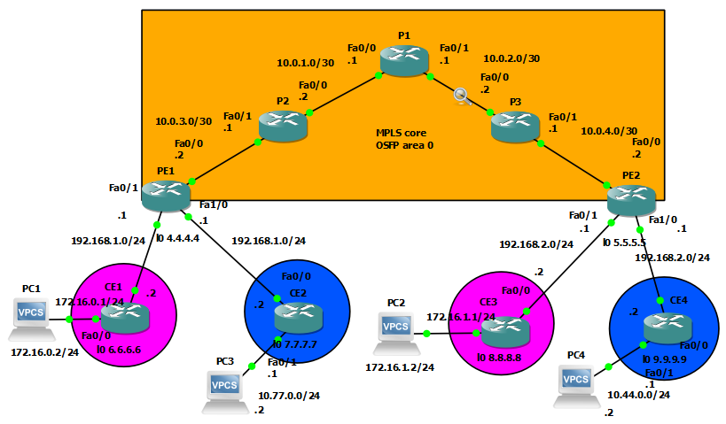
Configuring MPLS L3VPNs – Part 2
After finishing the MPLS configuration in this post, I thought to take a closer look at the MPLS network, especially the labels: with the help of Wireshark we can examine how the labels are being inserted, switched and eventually removed at the edge routers.
I initiated Wireshark packet captures between every router in the MPLS core network. After generating some traffic between PC1 and PC2 in the same VRF, we can examine ICMP Echo Request and Echo Reply packets: in this topology – with the Layer3 VPN-s – 2 MPLS headers are inserted between Layer 2 and Layer 3 (MPLS is often referred as Layer 2.5). Notice that the EtherType field is changed to 0x8847, signing that MPLS is being used above L2, not IPv4 or IPv6.
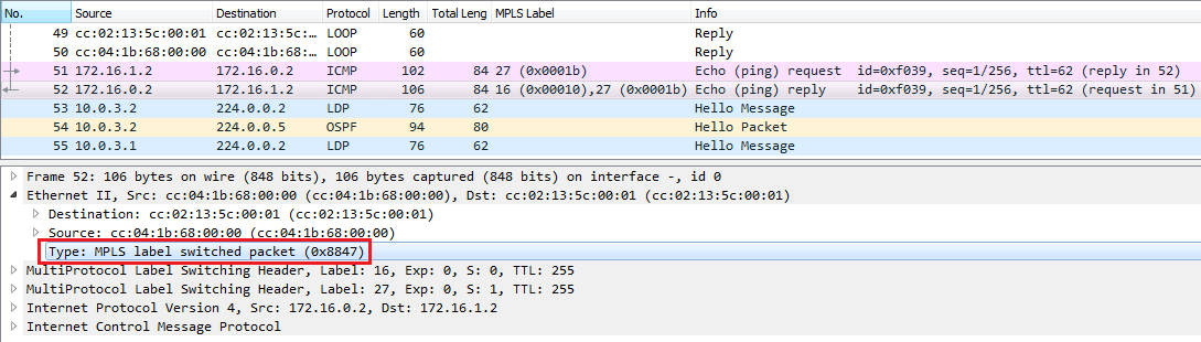
The first, outer label, sometimes called transport label (right above Layer 2) is indicating the Edge router, this label is swapped between the provider routers. The inner label called service label, identifies the costumer network (VRF), the Bottom of Stack bit of this label is set to 1, indicating that this is the last MPLS label, the upper layer is going to be IP. Notice that this label is unchanged between the provider routers, the provider routers only examine the outer label. The ingress edge router inserts this label, and the egress router removes it.
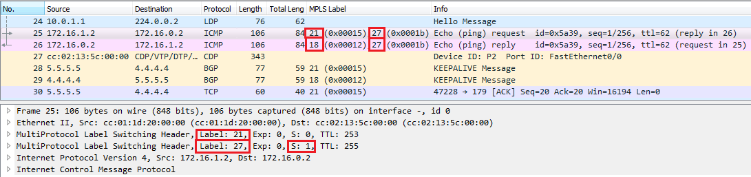
Let’s ping PC1 from PC2 and start a packet capture between PE2 and P3:
PC2> ping 172.16.0.2 -c 184 bytes from 172.16.0.2 icmp_seq=1 ttl=60 time=100.006 ms
Wireshark packet capture between PE2 and P3
Provider routers don’t do anything with the IP header, we can make sure of it by checking the TTL field in the IP header: the IP TTL value stays the same in the MPLS network.
We can notice that the inner (service) label which identifies the PURPLE VRF in this case is 27, and the outer label is 19. In the other direction (ICMP Echo Reply), P3 removes the outer label, only the inner label is attached to the packet, which PE2 eventually removes, and forwards the ICMP Ehco Reply as IP packet without using MPLS.
We can also take a look at PE2’s MPLS forwarding-table, we can see that the label 27 identifies the host in the PURPLE VRF, and we can probably guess that label 28 will be used for the hosts in the other VRF.
PE2#show mpls forwarding-tableLocal Outgoing Prefix Bytes tag Outgoing Next Hoptag tag or VC or Tunnel Id switched interface16 Pop tag 3.3.3.3/32 0 Fa0/0 10.0.4.117 16 1.1.1.1/32 0 Fa0/0 10.0.4.118 17 10.0.1.0/30 0 Fa0/0 10.0.4.119 Pop tag 10.0.2.0/30 0 Fa0/0 10.0.4.120 19 4.4.4.4/32 0 Fa0/0 10.0.4.121 20 2.2.2.2/32 0 Fa0/0 10.0.4.122 21 10.0.3.0/30 0 Fa0/0 10.0.4.123 Untagged 8.8.8.8/32[V] 0 Fa0/1 192.168.2.224 Aggregate 192.168.2.0/24[V] 163225 Untagged 9.9.9.9/32[V] 0 Fa1/0 192.168.2.226 Aggregate 192.168.2.0/24[V] 027 Untagged 172.16.1.0/24[V] 2842 Fa0/1 192.168.2.228 Untagged 10.44.0.0/24[V] 2842 Fa1/0 192.168.2.2PE2#
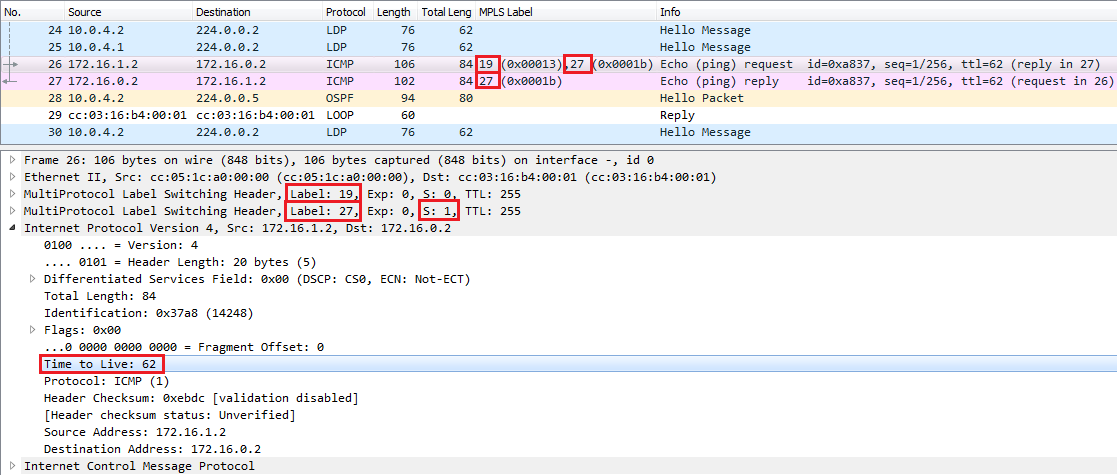
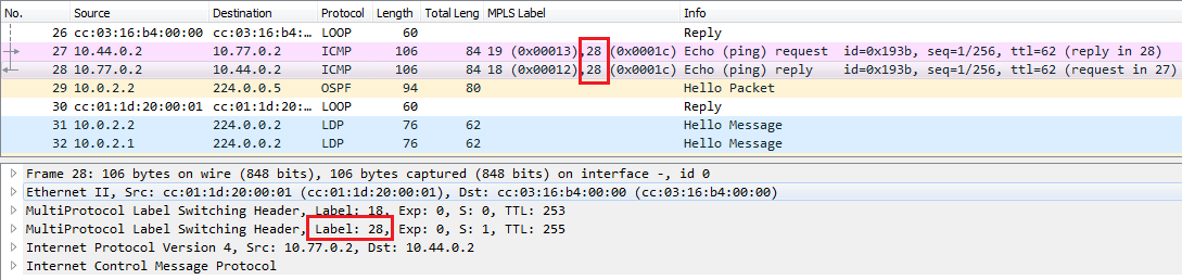
Let’s keep track of the ICMP messages: let’s see what’s happening between P3 and P1:
It seems like P3 didn’t do anything with ICMP Echo Request package, the outer label is the same. But notice that the MPLS TTL value has been decreased by 1 (the IP TTL stayed the same), so it suggests that something has happened with the outer MPLS label. We can check P3’s forwarding table, and discover that P3 swaps the label 19 for label 19 in this case, but it not necessarily stays the same. In the other direction (ICMP Echo Reply) P3 removes the outer label 18.
P3#show mpls forwarding-tableLocal Outgoing Prefix Bytes tag Outgoing Next Hoptag tag or VC or Tunnel Id switched interface16 Pop tag 1.1.1.1/32 0 Fa0/0 10.0.2.117 Pop tag 10.0.1.0/30 0 Fa0/0 10.0.2.118 Pop tag 5.5.5.5/32 12696 Fa0/1 10.0.4.219 19 4.4.4.4/32 15110 Fa0/0 10.0.2.120 20 2.2.2.2/32 0 Fa0/0 10.0.2.121 21 10.0.3.0/30 0 Fa0/0 10.0.2.1P3#P3#show mpls ip binding1.1.1.1/32in label: 16out label: imp-null lsr: 1.1.1.1:0 inuseout label: 17 lsr: 5.5.5.5:02.2.2.2/32in label: 20out label: 20 lsr: 1.1.1.1:0 inuseout label: 21 lsr: 5.5.5.5:03.3.3.3/32in label: imp-nullout label: 16 lsr: 1.1.1.1:0out label: 16 lsr: 5.5.5.5:04.4.4.4/32in label: 19out label: 19 lsr: 1.1.1.1:0 inuseout label: 20 lsr: 5.5.5.5:05.5.5.5/32in label: 18out label: imp-null lsr: 5.5.5.5:0 inuseout label: 18 lsr: 1.1.1.1:0
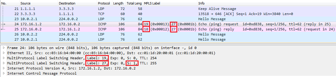
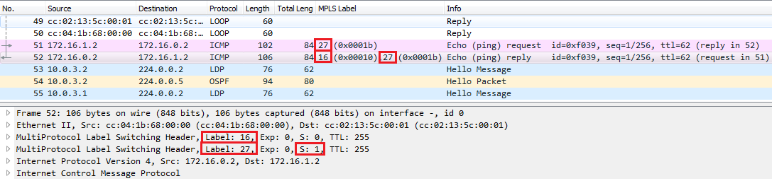
Let’s follow the ICMP ping and see the Wireshark capture between P1 and P2.
Notice that P1 swaps the outer label 19 for label 21 forwarding the Echo Request and swaps the label 18 for label 18 forwarding the Echo Reply, let’s see some show commands on P1 and P2:
P1#show mpls forwarding-tableLocal Outgoing Prefix Bytes tag Outgoing Next Hoptag tag or VC or Tunnel Id switched interface16 Pop tag 3.3.3.3/32 0 Fa0/1 10.0.2.217 Pop tag 10.0.4.0/30 0 Fa0/1 10.0.2.218 18 5.5.5.5/32 16367 Fa0/1 10.0.2.219 21 4.4.4.4/32 19715 Fa0/0 10.0.1.220 Pop tag 2.2.2.2/32 0 Fa0/0 10.0.1.221 Pop tag 10.0.3.0/30 0 Fa0/0 10.0.1.2
P2#show mpls forwarding-tableLocal Outgoing Prefix Bytes tag Outgoing Next Hoptag tag or VC or Tunnel Id switched interface16 18 5.5.5.5/32 13459 Fa0/0 10.0.1.117 16 3.3.3.3/32 0 Fa0/0 10.0.1.118 Pop tag 1.1.1.1/32 0 Fa0/0 10.0.1.119 17 10.0.4.0/30 0 Fa0/0 10.0.1.120 Pop tag 10.0.2.0/30 0 Fa0/0 10.0.1.121 Pop tag 4.4.4.4/32 14737 Fa0/1 10.0.3.2
P2 removes the outer MPLS label (21), and in the other direction swaps label 16 for label 18 forwarding the ICMP Echo Reply.
PE1 removes the inner label, and forwards the Echo Request as IP packet towards the host in the designated VRF which is indicated by the inner label. In the other direction PE2 inserts both two labels between the Layer 2 and Layer 3 header.
How is the traffic forwarded between the hosts in the other VRF? Pretty much the same, except that the inner label is different, instead of 27, label 28 is assigned. The outer labels are exactly the same, since the paths of the packets in the MPLS network are the same.
PE1#show mpls forwarding-tableLocal Outgoing Prefix Bytes tag Outgoing Next Hoptag tag or VC or Tunnel Id switched interface16 16 5.5.5.5/32 0 Fa0/0 10.0.3.117 17 3.3.3.3/32 0 Fa0/0 10.0.3.118 Pop tag 2.2.2.2/32 0 Fa0/0 10.0.3.119 18 1.1.1.1/32 0 Fa0/0 10.0.3.120 19 10.0.4.0/30 0 Fa0/0 10.0.3.121 20 10.0.2.0/30 0 Fa0/0 10.0.3.122 Pop tag 10.0.1.0/30 0 Fa0/0 10.0.3.123 Untagged 6.6.6.6/32[V] 696 Fa0/1 192.168.1.224 Aggregate 192.168.1.0/24[V] 025 Untagged 7.7.7.7/32[V] 0 Fa1/0 192.168.1.226 Aggregate 192.168.1.0/24[V] 027 Untagged 172.16.0.0/24[V] 4980 Fa0/1 192.168.1.228 Untagged 10.77.0.0/24[V] 2940 Fa1/0 192.168.1.2
Let’s examine one more thing. What is the maximum TCP segment size (the TCP payload) we can transfer without fragmentation. The MTU is the default value of 1500 byte everywhere. Knowing that each MPLS header which are inserted additionally are 4 bytes, let’s do some calculation: 1500 byte (MTU) – 2 x 4 byte (MPLS headers) – 20 byte IP header – 32 byte TCP header (with options of 12 bytes) = 1440 byte. According to my calculation the maximum amount of TCP payload we can transfer without fragmentation is 1440 byte. We can prove that with the default hosts included in GNS3, I initiated 2 TCP connections (with the full 3-way TCP handshake) with the specified source and destination port while capturing packets with Wireshark. In the first TCP connection I specified a TCP payload of 1440 bytes, while in the second TCP connection a payload of 1441 bytes, and the ‘Do not fragment’ bit wasn’t set by default. So we expect the second TCP payload to be fragmented. Here are the commands I’ve issued on PC2, and the Wireshark capture.
PC2> ping 172.16.0.2 -3 -c 1 -p 5555 -s 4444 -l 1440Connect 5555@172.16.0.2 seq=1 ttl=60 time=93.006 msSendData 5555@172.16.0.2 seq=1 ttl=60 time=90.005 msClose 5555@172.16.0.2 seq=1 ttl=60 time=89.005 msPC2> ping 172.16.0.2 -3 -c 1 -p 5555 -s 4444 -l 1441Connect 5555@172.16.0.2 seq=1 ttl=60 time=83.004 msSendData 5555@172.16.0.2 seq=1 ttl=60 time=99.006 msClose 5555@172.16.0.2 seq=1 ttl=60 time=95.005 ms
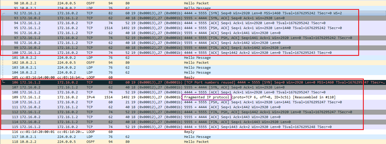
Because of the additional MPLS headers the MSS we can transfer is reduced. If we want to transfer the same amount of TCP payload as without MPLS we can also increase the MTU value, but we would have to do that everywhere.