Implementing Site-to-Site IPsec VPN: GRE over IPsec and MTU issues (Part 3)
In the previous post I created the VPN tunnel between the two sites with a crypto map. This implementation is very static, the ACLs define the traffic what we want to protect and send through the tunnel. Dynamic routing is not supported, both peers must have static route in their RIB to reach the remote site (which can be the default route). To solve this issue we're going to set up a GRE tunnel between R1 and R3 using the previous topology:
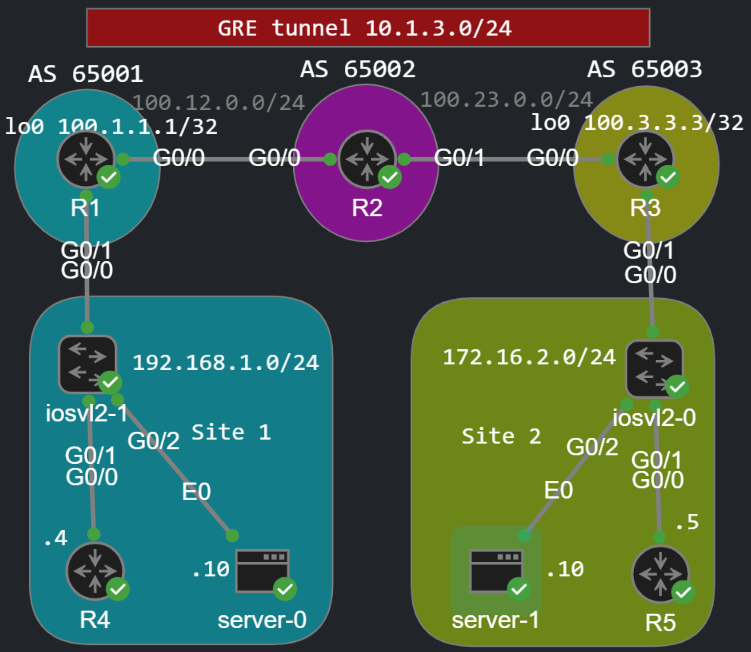
Multicast is supported with GRE, so we can establish an OSPF adjacency between R1 and R3 though the virtual tunnel interface. The problem is that GRE send everything in plain text, so we're going to protect the GRE tunnel with IPsec to provide confidentiality.
Building the GRE tunnel between R1 and R3
This time we're going to establish the tunnel between the loopbacks of R1 and R3. So first the routers must be able to reach the loopback address of each other, so we have to advertise the loopbacks with BGP:
R1(config)#int lo0R1(config-if)#ip address 100.1.1.1 255.255.255.255R1(config)#router bgp 65001R1(config-router)#network 100.1.1.1 mask 255.255.255.255R3(config)#int lo0R3(config-if)#ip address 100.3.3.3 255.255.255.255R3(config)#router bgp 65003R3(config-router)#network 100.3.3.3 mask 255.255.255.255
Now the routers can reach each other via their loopback address:
R3(config-router)#do show bgp ipv4 unicast | beg Netw Network Next Hop Metric LocPrf Weight Path *> 0.0.0.0 100.23.0.2 0 65002 i *> 100.1.1.1/32 100.23.0.2 0 65002 65001 i *> 100.3.3.3/32 0.0.0.0 0 32768 iR3(config-router)#do ping 100.1.1.1 source lo0Type escape sequence to abort.Sending 5, 100-byte ICMP Echos to 100.1.1.1, timeout is 2 seconds:Packet sent with a source address of 100.3.3.3 !!!!!Success rate is 100 percent (5/5), round-trip min/avg/max = 2/2/3 ms
Next we create the tunnel interfaces on both routers. The tunnel mode is GRE by default, so we don't have to change that, the tunnel source is the loopback0 address on both routers, and the tunnel destination is the loopback of the remote peer:
R1(config)#int tunnel 0R1(config-if)#tunnel source lo0R1(config-if)#tunnel destination 100.3.3.3 R1(config-if)#ip address 10.1.3.1 255.255.255.0R1(config-if)#ip ospf 1 area 0R1(config-if)#int g0/1R1(config-if)#ip ospf 1 area 0R3(config)#int tun0R3(config-if)#tunnel source lo0R3(config-if)#tunnel destination 100.1.1.1R3(config-if)#ip address 10.1.3.3 255.255.255.0R3(config-if)#ip ospf 1 area 0R3(config-if)#int g0/1R3(config-if)#ip ospf 1 area 0
Besides that we enable OSPF on the tunnel interface and on the G0/1 interface advertising the 192.168.1.0/24 and the 172.16.2.0/24 subnets (don't enable OSPF on the WAN interface!). Now R1 and R3 should become OSPF neighbors:
%OSPF-5-ADJCHG: Process 1, Nbr 100.1.1.1 on Tunnel0 from LOADING to FULL, Loading Done
Now R1 and R3 can reach the remote subnet through the tunnel0 interface. Here is the routing table of R3 for example:
R3#show ip route ospf | beg GateGateway of last resort is 100.23.0.2 to network 0.0.0.0O 192.168.1.0/24 [110/1001] via 10.1.3.1, 00:05:17, Tunnel0
If I run a traceroute from R4 to R5, the trace shows that R5 is three hops away from R4. The network between R1 and R3 is hidden:
R4#traceroute 172.16.2.5 numeric Type escape sequence to abort.Tracing the route to 172.16.2.5VRF info: (vrf in name/id, vrf out name/id) 1 192.168.1.1 2 msec 3 msec 2 msec 2 10.1.3.3 4 msec 3 msec 4 msec 3 172.16.2.5 5 msec * 5 msec
So what's the problem with GRE? Everything is sent in clear text:
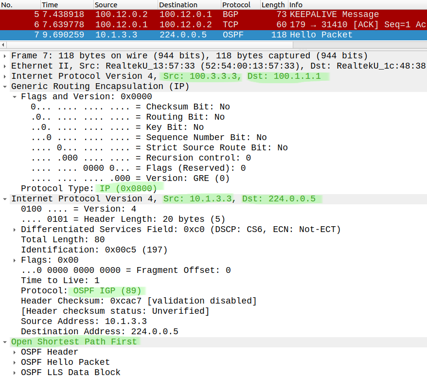
If an attacker starts capturing packets anywhere between R1 and R3 he could see everything. Now we want to secure the tunnel using IPsec.
Securing the GRE tunnel with IPsec
We create the ISAKMP policy and the transform-set the same way as in the previous post:
R1(config)#do show run | sec cryptocrypto isakmp policy 10 encr aes 256 hash sha256 authentication pre-share group 19R1(config)#crypto isakmp key cisco123 address 100.3.3.3R3(config)#crypto isakmp key cisco123 address 100.1.1.1R1(config)#crypto ipsec transform-set TRSET esp-aes 256 esp-sha-hmac R3(config)#crypto ipsec transform-set TRSET esp-aes 256 esp-sha-hmac
The difference is that we don't use a crypto map this time. Technically we could also use a crypto map and define the proxy ACL as permit gre host 100.1.1.1 host 100.3.3.3 from R1's perspective, and apply the crypto map to the physical interface (NOT to the tunnel interface!). This would work, but we don't do that. We are going to use IPsec profiles. The IPsec profile will be applied to the tunnel interface, the tunnel already specifies the interesting traffic, so we don't need to specify the destination peer and the proxy ACL. The transform-set will be called form the IPsec profile:
R1(config)#crypto ipsec profile PROFR1(ipsec-profile)#set transform-set TRSET
And finally we apply the ipsec profile to the tunnel interface on both routers:
R1(config)#int tun 0R1(config-if)#tunnel protection ipsec profile PROFR3(config)#int tun 0R3(config-if)#tunnel protection ipsec profile PROF
That's all we need, the traffic sent through the tunnel now will be encrypted since we use ESP with AES-256 as we've seen in the previous post. We establish the tunnel the same way: Main Mode for Phase 1 and Quick Mode for Phase 2. After that everything will be ESP encapsulated and effectively encrypted:
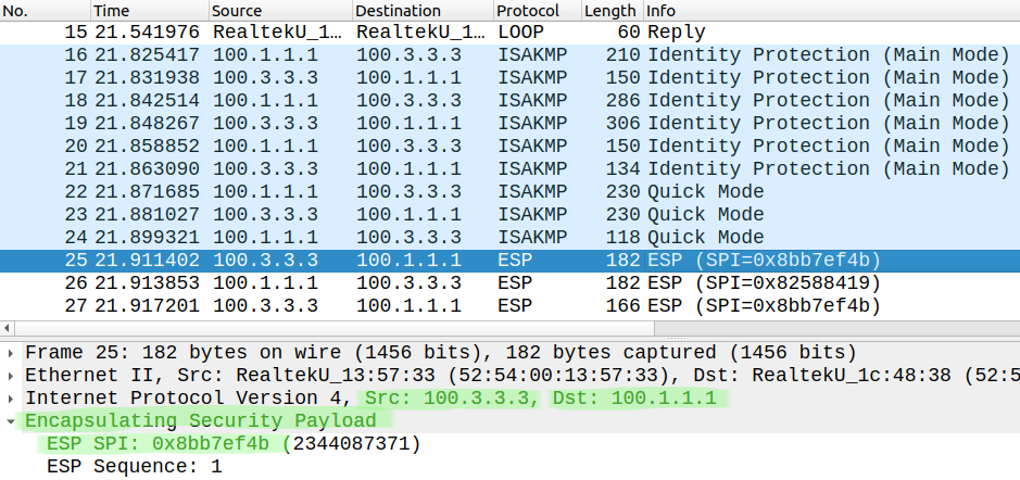
For verification we use the same commands. Now we should have two Phase 1 ISAKMP SAs:
R1#show crypto isakmp saIPv4 Crypto ISAKMP SAdst src state conn-id status100.1.1.1 100.3.3.3 QM_IDLE 1002 ACTIVE100.3.3.3 100.1.1.1 QM_IDLE 1001 ACTIVE
And two IPsec (Phase 2) SAs:
R1#show crypto ipsec sainterface: Tunnel0 Crypto map tag: Tunnel0-head-0, local addr 100.1.1.1 protected vrf: (none) local ident (addr/mask/prot/port): (100.1.1.1/255.255.255.255/47/0) remote ident (addr/mask/prot/port): (100.3.3.3/255.255.255.255/47/0) current_peer 100.3.3.3 port 500 PERMIT, flags={origin_is_acl,} #pkts encaps: 33, #pkts encrypt: 33, #pkts digest: 33 #pkts decaps: 33, #pkts decrypt: 33, #pkts verify: 33 #pkts compressed: 0, #pkts decompressed: 0 #pkts not compressed: 0, #pkts compr. failed: 0 #pkts not decompressed: 0, #pkts decompress failed: 0 #send errors 0, #recv errors 0 local crypto endpt.: 100.1.1.1, remote crypto endpt.: 100.3.3.3 plaintext mtu 1438, path mtu 1500, ip mtu 1500, ip mtu idb GigabitEthernet0/0 current outbound spi: 0xD0AF1D21(3501137185) PFS (Y/N): N, DH group: none inbound esp sas: spi: 0xFA8E725A(4203639386) transform: esp-256-aes esp-sha-hmac , in use settings ={Tunnel, } conn id: 3, flow_id: SW:3, sibling_flags 80000040, crypto map: Tunnel0-head-0 sa timing: remaining key lifetime (k/sec): (4272027/3403) IV size: 16 bytes replay detection support: Y Status: ACTIVE(ACTIVE) inbound ah sas: inbound pcp sas: outbound esp sas: spi: 0xD0AF1D21(3501137185) transform: esp-256-aes esp-sha-hmac , in use settings ={Tunnel, } conn id: 4, flow_id: SW:4, sibling_flags 80000040, crypto map: Tunnel0-head-0 sa timing: remaining key lifetime (k/sec): (4272027/3403) IV size: 16 bytes replay detection support: Y Status: ACTIVE(ACTIVE) outbound ah sas: outbound pcp sas:
MTU issues
Now let's take a look how the GRE tunneling and IPsec encryption affect the throughput: what's the maximum packet size we can send though? First let's try to send a regular 1500 byte packet with the DF-bit: this is a field in the IP header, if the DF-bit is set to 1 the routers cannot fragment the packet so we can determine the MTU.
R4#ping 172.16.2.5 size 1500 df-bitType escape sequence to abort.Sending 5, 1500-byte ICMP Echos to 172.16.2.5, timeout is 2 seconds:Packet sent with the DF bit setM.M.MSuccess rate is 0 percent (0/5)
Now we have 'M's meaning that the router cannot fragment the packet. Let's try to determine what's the maximum packet size we can send through without fragmentation. To do that we run a ping sweep. We run an extended ping with increasing sizes of payload starting from 1400 bytes to 1450 bytes:
Sending 51, [1400..1450]-byte ICMP Echos to 172.16.2.5, timeout is 2 seconds:Packet sent with a source address of 192.168.1.4Packet sent with the DF bit setReply to request 0 (10 ms) (size 1400)Reply to request 1 (9 ms) (size 1401)Reply to request 2 (9 ms) (size 1402)Reply to request 3 (9 ms) (size 1403)Reply to request 4 (9 ms) (size 1404)Reply to request 5 (9 ms) (size 1405)Reply to request 6 (8 ms) (size 1406)Reply to request 7 (9 ms) (size 1407)Reply to request 8 (8 ms) (size 1408)Reply to request 9 (8 ms) (size 1409)Reply to request 10 (9 ms) (size 1410)Reply to request 11 (8 ms) (size 1411)Reply to request 12 (8 ms) (size 1412)Reply to request 13 (9 ms) (size 1413)Reply to request 14 (8 ms) (size 1414)Unreachable from 192.168.1.1, maximum MTU 1414 (size 1415)Request 16 timed out (size 1416)Unreachable from 192.168.1.1, maximum MTU 1414 (size 1417)Request 18 timed out (size 1418)<...output omitted...>
So the MTU should be 1414 bytes according to the output above. Couldn't we just calculate this beforehand? Actually not really, this value is very hard to predict, many things depend on the AES block encryption size, usually we just pick a general value which is usually 1400 bytes. If we had just GRE without IPsec, the calculation would be very simple: we have an additional IP header (-20 bytes) and a GRE header (-4 bytes), so without IPsec the MTU would reduce by 24 bytes. With IPsec and encryption we can't calculate this exactly. So a packet with 1415 bytes should not go though without fragmentation:
R4#ping 172.16.2.5 df-bit size 1415Type escape sequence to abort.Sending 5, 1415-byte ICMP Echos to 172.16.2.5, timeout is 2 seconds:Packet sent with the DF bit setM.M.MSuccess rate is 0 percent (0/5)
But why do we do really care about fragmentation? Because fragmentation is done by the CPU on the routers, the packets will be software-switched which is not just slow but it can also hit the CPU utilization. We should offload the fragmentation to the end hosts, the encrypted packets should not be fragmented, the routers should only do the encryption. So again as rule of thumb we just pick 1400 bytes and set MTU on the tunnel interface. And end hosts supporting Path MTU Discovery (PMTUD) should adjust their MTU to 1400 bytes.
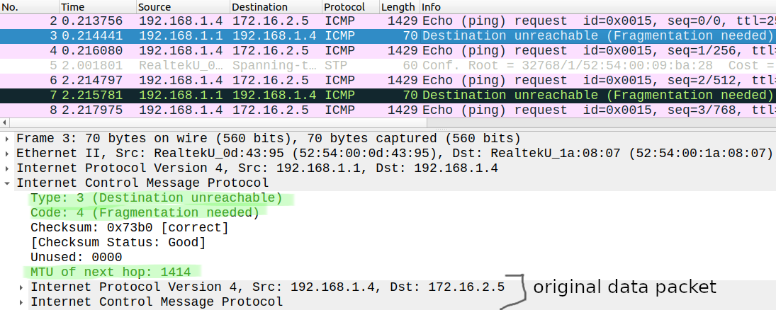
PMTUD works just as we can see above in Wireshark: the hosts send packets with the DF-bit set to 1, any device along the path with smaller MTU drops the packet and sends back an ICMP Destination Unreachable Fragmentation needed message. We can see in the ICMP message that the MTU is 1414 bytes the same value we've determined with the ping sweep. But let's just set the MTU to 1400 bytes on both sides:
R1(config)#int tun0R1(config-if)#ip mtu 1400R1(config-if)#ip tcp adjust-mss 1360R3(config)#int tun 0R3(config-if)#ip mtu 1400R3(config-if)#ip tcp adjust-mss 1360
Additionally I've also issued theip tcp adjust-mss 1360command, this can be advantageous if the end hosts doesn't support PMTUD. But first let's verify that the MTU has changed:
R4#ping 172.16.2.5 df-bit size 1401Type escape sequence to abort.Sending 5, 1401-byte ICMP Echos to 172.16.2.5, timeout is 2 seconds:Packet sent with the DF bit setM.M.MSuccess rate is 0 percent (0/5)R4#ping 172.16.2.5 df-bit size 1400Type escape sequence to abort.Sending 5, 1400-byte ICMP Echos to 172.16.2.5, timeout is 2 seconds:Packet sent with the DF bit set!!!!!Success rate is 100 percent (5/5), round-trip min/avg/max = 7/7/8 ms
The maximum size of packets we can send though is now 1400 bytes, we would need fragmentation to send 1401 bytes. But what does the ip tcp adjust-mss 1360command do exactly? It modifies the MSS in the TCP header when the hosts send their first TCP SYN packet. Let's test this with the Linux servers located at both sides, here I set the IP address and the default gateway for both servers:
cisco@SERVER0:~$ sudo ifconfig eth0 192.168.1.10 netmask 255.255.255.0 upcisco@SERVER0:~$ sudo route add -net 0.0.0.0/0 dev eth0cisco@SERVER1:~$ sudo ifconfig 172.16.2.10 netmask 255.255.255.0 upcisco@SERVER1:~$ sudo route add -net 0.0.0.0/0 dev eth0
Now let's try to initiate a TCP session from Server1 to Server0:
cisco@SERVER1:~$ telnet 192.168.1.10telnet: can't connect to remote host (192.168.1.10): Connection refused
Server0 doesn't run telnet, so the port is closed, but that's not the point. Here is the TCP SYN packet which R1 forwards to Server0:
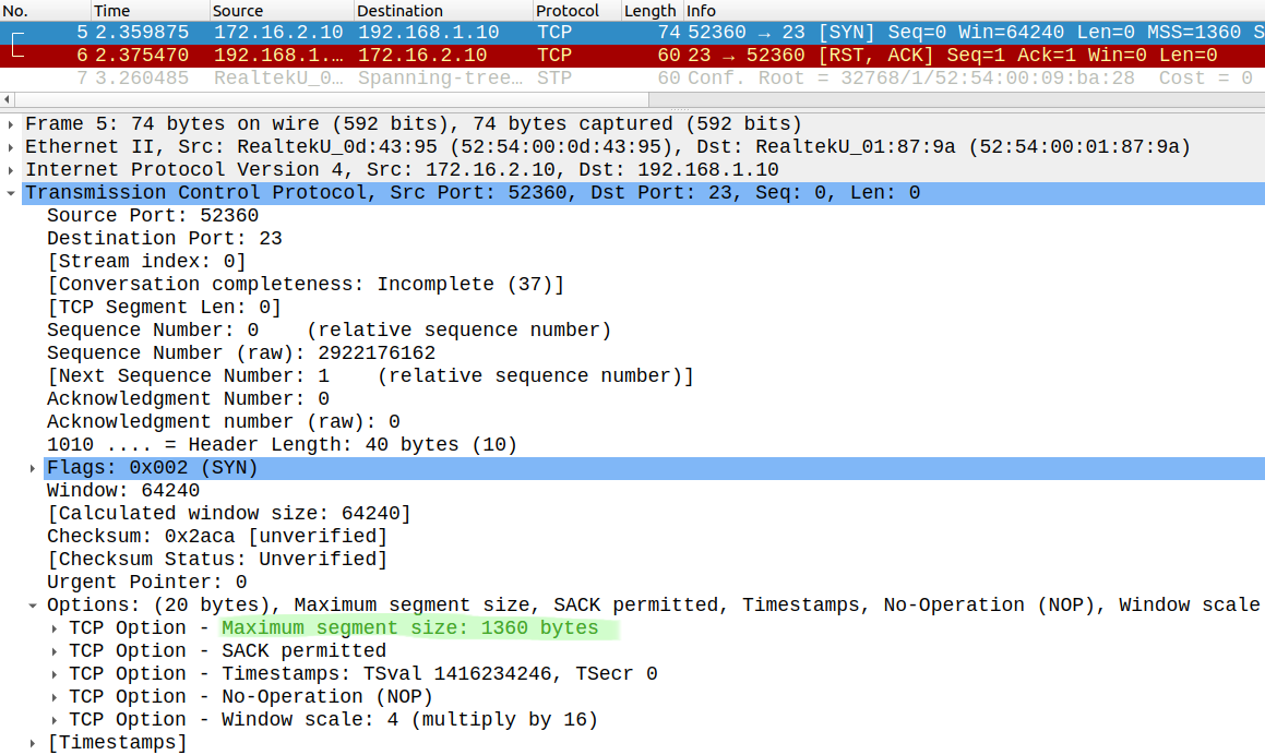
Look at the MSS: it is set to 1360 by the router. So if Server1 sends the TCP SYN with a higher MSS initially, the routers change that to 1360. This way we can also restrict size of the TCP payload that the end hosts can send to avoid fragmentation.