Implementing Inter-AS MPLS L3VPN services with Option A
What if a single customer wants to have an MPLS L3VPN service, but he has to connect with his CE routers to two different service providers? Let's assume that the CE routers are geographically separated and multiple service providers are involved: the PE on site one belongs to ISP1, and the remote PE on site two belongs to ISP2, but still the customer is the same, he has CE routers on both sites. In this case there has to be some cooperation between the service providers, basically we have three options how we can configure such a scenario between the service providers. In this first post we take a look at Option A.
About the topology and what I have already preconfigured
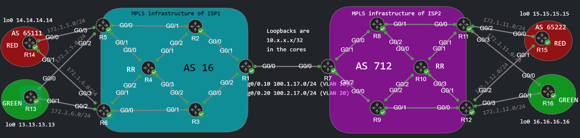
In this example we have two customers: customer RED and GREEN. Both have a CE router at two sites and connect to two different PEs for redundancy. The PEs on the left (R5 and R6) belong to ISP1 and the PEs on the right (R11 and R12) belong to ISP2. Customer RED runs BGP as the PE-CE routing protocol with his private ASNs (AS 65111 and AS 65222), while customer GREEN runs OSPF as PE-CE protocol on both of his devices (R13 and R16). I'm not going to delve into the details how we configure intra-AS L3VPN: VRFs, VPNv4, MP-BGP, Route Distinguisher/Route Target, redistribution etc. You have to know all of these if you want to understand the inter-AS implementation as well. At this point we don't run any routing protocol between the two ISPs (R1 - R7): no BGP, no LDP, nothing. So this is our starting point: I have already put the customer facing interfaces into different VRFs, set up the VPNv4 BGP neighborship within the ISPs MPLS infrastructure and set up the OSPF/BGP neighborships with the customers and redistributed the routes for customer GREEN (OSPF into BGP and BGP into OSPF). Also both ISPs have MPLS enabled in the core by using LDP. This is how the relevant config looks like on R5 for example:
R5#show run | sec bgp|ospf 2router ospf 2 vrf GREEN redistribute bgp 16 subnets network 172.2.5.5 0.0.0.0 area 0router bgp 16 bgp log-neighbor-changes no bgp default ipv4-unicast neighbor 10.4.4.4 remote-as 16 neighbor 10.4.4.4 update-source Loopback0 ! address-family ipv4 exit-address-family ! address-family vpnv4 neighbor 10.4.4.4 activate neighbor 10.4.4.4 send-community extended neighbor 10.4.4.4 route-reflector-client exit-address-family ! address-family ipv4 vrf GREEN redistribute ospf 2 match internal external 1 external 2 exit-address-family ! address-family ipv4 vrf RED neighbor 172.1.5.14 remote-as 65111 neighbor 172.1.5.14 activate exit-address-family
and on R6:
R6#show run | sec bgp|ospf 2router ospf 2 vrf GREEN redistribute bgp 16 subnets network 172.2.6.6 0.0.0.0 area 0router bgp 16 bgp log-neighbor-changes no bgp default ipv4-unicast neighbor 10.4.4.4 remote-as 16 neighbor 10.4.4.4 update-source Loopback0 ! address-family ipv4 exit-address-family ! address-family vpnv4 neighbor 10.4.4.4 activate neighbor 10.4.4.4 send-community extended exit-address-family ! address-family ipv4 vrf GREEN redistribute ospf 2 match internal external 1 external 2 exit-address-family ! address-family ipv4 vrf RED neighbor 172.1.6.14 remote-as 65111 neighbor 172.1.6.14 activate exit-address-family
Basically the other side (ISP2) is just a mirror image of this, the IP addresses are different of course, but the VRFs, the BGP setup, the whole concept is the same. Except the Route Targets (RT). But we'll take a look at that later in details. We use R4 (10.4.4.4) as a Route Reflector (RR) for ISP1, and the same thing on the other side: ISP2 uses R10 (10.10.10.10) as the Route Reflector. The RR is not really relevant here in Option A, you can set this up without a RR, but with Option C the RR is going to be important, because we'll establish the VPNv4 session between the two RRs.
Why Option A? Downsides/Advantages
Option A is probably the easiest to set up from the three. But it has some drawbacks: it is the the least scalable. For every customer we need a separate, dedicated interface on R1 and R7, just like on the real customer facing PEs. Actually with Option A, R1 and R7 are also PEs from the perspective of the neighbor ISP. ISP1 treats ISP2 as a customer and vice versa, sometimes this is called 'back-to-back VRF'. But this option might be the most secure of the three: the ISPs don't have to share anything with each other from their own infrastructure. Not even the RTs. The import/export RTs doesn't have to match on the two sites. They are only locally significant, by locally I mean only within each SPs infrastructure. But if we had 1000 customer we'd need 1000 dedicated interfaces between R1 and R7. They can be subinterfaces of course tagged with 802.1Q, it's not really feasible to have 1000 dedicated physical interfaces. So Option A really lacks scalability. What about the link between R1 and R7? That's going to be an unlabeled segment: the routers remove the labels and just send an unlabeled, IP packet to each other. The remote PE on the other side (R1 or R7) then imposes a new label stack to the IP packet and sends a labeled packet to the 'real', customer facing PE. So we won't have an LSP end-to-end.
Implementing Option A, Pitfalls
Let's see if we can receive the customer prefixes from the PEs on the RR:
R4#show bgp vpnv4 unicast all | begin Net Network Next Hop Metric LocPrf Weight PathRoute Distinguisher: 16:1 * i 14.14.14.14/32 10.6.6.6 0 100 0 65111 i *>i 10.5.5.5 0 100 0 65111 iRoute Distinguisher: 16:2 * i 13.13.13.13/32 10.6.6.6 2 100 0 ? *>i 10.5.5.5 2 100 0 ? * i 172.2.5.0/24 10.6.6.6 2 100 0 ? *>i 10.5.5.5 0 100 0 ? *>i 172.2.6.0/24 10.6.6.6 0 100 0 ? * i 10.5.5.5 2 100 0 ?
Yes we can. R4 also peers with R1 as a RR-client, let's see if R1 can receive the prefixes:
R1#debug bgp vpnv4 unicast updates BGP updates debugging is on for address family: VPNv4 Unicast R1#clear ip bgp * inBGP(4): 10.4.4.4 rcvd UPDATE w/ attr: nexthop 10.5.5.5, origin i, localpref 100, metric 0, originator 10.5.5.5, clusterlist 10.4.4.4, merged path 65111, AS_PATH , extended community RT:16:10BGP(4): 10.4.4.4 rcvd 16:1:14.14.14.14/32, label 16 -- DENIED due to: extended community not supported;
R1 can't accept the prefixes: extended community not supported . This is because we don't have any import RTs. R1 doesn't connect to any customer, so we don't have any VRF defined on R1, so we don't have any import RTs. Notice that the RR (R4) also doesn't have any VRF, but he can forward the VPNv4 prefixes because it is a RR. But R1 needs to have the VRFs, with the same import RT as it was exported on the PEs. Regarding the VRFs, this is what we have on both R5 and R6 (their VRF configuration is identical):
R5#show run | sec vrf def vrf definition GREEN rd 16:2 route-target export 16:20 route-target import 16:20 ! address-family ipv4 exit-address-familyvrf definition RED rd 16:1 route-target export 16:10 route-target import 16:10 ! address-family ipv4 exit-address-family
The RDs don't have to match of course on R5 and R6, but in this case they do. Next I simply copy-paste the VRF definitions above to R1. And the moment I do this R1 can import the VPNv4 prefixes and put them into his BGP table:
R1(config)#do show bgp vpnv4 unicast all | sec Net Network Next Hop Metric LocPrf Weight PathRoute Distinguisher: 16:1 (default for vrf RED) *>i 14.14.14.14/32 10.5.5.5 0 100 0 65111 iRoute Distinguisher: 16:2 (default for vrf GREEN) *>i 13.13.13.13/32 10.5.5.5 2 100 0 ? *>i 172.2.5.0/24 10.5.5.5 0 100 0 ? *>i 172.2.6.0/24 10.6.6.6 0 100 0 ?
Next we create the subinterfaces and put them into different customer VRFs:
interface GigabitEthernet0/0.10 encapsulation dot1Q 10 vrf forwarding RED ip address 100.1.17.1 255.255.255.0endinterface GigabitEthernet0/0.20 encapsulation dot1Q 20 vrf forwarding GREEN ip address 100.2.17.1 255.255.255.0end
We can choose the VLAN number of course, but it has to match with the remote side. At this point we haven't set up any routing between the two ISPs. Next let's move to the other side, to ISP2. We basically have the same issue here, R7 can't import the VPNv4 prefixes, because it doesn't have any VRFs. This is what the RR (R10) has at this point:
R10#show bgp vpnv4 unicast all | beg Net Network Next Hop Metric LocPrf Weight PathRoute Distinguisher: 16:11 * i 15.15.15.15/32 10.12.12.12 0 100 0 65222 i *>i 10.11.11.11 0 100 0 65222 iRoute Distinguisher: 16:22 * i 16.16.16.16/32 10.12.12.12 2 100 0 ? *>i 10.11.11.11 2 100 0 ? * i 172.2.11.0/24 10.12.12.12 2 100 0 ? *>i 10.11.11.11 0 100 0 ? *>i 172.2.12.0/24 10.12.12.12 0 100 0 ? * i 10.11.11.11 2 100 0 ?
And these are the VRF definition on the two PEs, R11 and R12 (they are identical):
R11(config)#do show run | sec vrf defvrf definition GREEN rd 16:22 route-target export 16:200 route-target import 16:200 ! address-family ipv4 exit-address-familyvrf definition RED rd 16:11 route-target export 16:100 route-target import 16:100 ! address-family ipv4 exit-address-family
Notice that the RTs are not the same as within the infrastructure of ISP1. And they doesn't have to be same. The import/export RTs only have to be the same between R1 and R5/R6 and between R7 and R11/R12. So I simply copy-paste the VRF definitions above to R7, so that it also can accept the VPNv4 prefixes. Next I create the subinterfaces on R7 the same way as on R1:
interface GigabitEthernet0/0.10 encapsulation dot1Q 10 vrf forwarding RED ip address 100.1.17.7 255.255.255.0endinterface GigabitEthernet0/0.20 encapsulation dot1Q 20 vrf forwarding GREEN ip address 100.2.17.7 255.255.255.0end
And finally, the last step: we establish an IPv4 unicast BGP session (NOT VPNv4!) between R1 and R7 by using the subinterfaces:
R1: address-family ipv4 vrf GREEN neighbor 100.2.17.7 remote-as 712 neighbor 100.2.17.7 activate exit-address-family ! address-family ipv4 vrf RED neighbor 100.1.17.7 remote-as 712 neighbor 100.1.17.7 activate exit-address-family
R7: address-family ipv4 vrf GREEN neighbor 100.2.17.1 remote-as 16 neighbor 100.2.17.1 activate exit-address-family ! address-family ipv4 vrf RED neighbor 100.1.17.1 remote-as 16 neighbor 100.1.17.1 activate exit-address-family
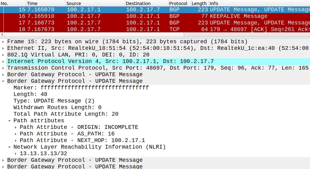
Now R1 and R7 learn the prefixes from the other side:
R1#show bgp vpnv4 unicast all | begin Net Network Next Hop Metric LocPrf Weight PathRoute Distinguisher: 16:1 (default for vrf RED) *>i 14.14.14.14/32 10.5.5.5 0 100 0 65111 i *> 15.15.15.15/32 100.1.17.7 0 712 65222 iRoute Distinguisher: 16:2 (default for vrf GREEN) *>i 13.13.13.13/32 10.5.5.5 2 100 0 ? *> 16.16.16.16/32 100.2.17.7 0 712 ? *>i 172.2.5.0/24 10.5.5.5 0 100 0 ? *>i 172.2.6.0/24 10.6.6.6 0 100 0 ? *> 172.2.11.0/24 100.2.17.7 0 712 ? *> 172.2.12.0/24 100.2.17.7 0 712 ?
The customers also learn the routes of the remote site. Here is the routing table of R13 for example, he learns the prefixes of the remote site as O E2 external routes:
R13#show ip route | sec O EO E2 16.16.16.16 [110/1] via 172.2.6.6, 00:18:27, GigabitEthernet0/1 [110/1] via 172.2.5.5, 00:18:27, GigabitEthernet0/0 172.2.0.0/16 is variably subnetted, 6 subnets, 2 masksO E2 172.2.11.0/24 [110/1] via 172.2.6.6, 00:18:27, GigabitEthernet0/1 [110/1] via 172.2.5.5, 00:18:27, GigabitEthernet0/0O E2 172.2.12.0/24 [110/1] via 172.2.6.6, 00:18:27, GigabitEthernet0/1 [110/1] via 172.2.5.5, 00:18:27, GigabitEthernet0/0
Now we have reachability between the remote sites of customers, but notice that the path between R1 and R7 is an unlabeled path, the routers send each other an IP packet without MPLS labels:
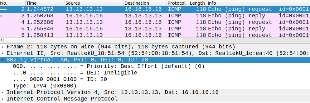
We can also verify this with a traceroute from a CE:
R14#traceroute 15.15.15.15 source lo0 numeric Type escape sequence to abort.Tracing the route to 15.15.15.15VRF info: (vrf in name/id, vrf out name/id) 1 172.1.5.5 3 msec 2 msec 2 msec 2 10.0.25.2 [MPLS: Labels 2005/1011 Exp 0] 4 msec 4 msec 4 msec 3 100.1.17.1 [MPLS: Label 1011 Exp 0] 2 msec 2 msec 3 msec 4 100.1.17.7 3 msec 4 msec 3 msec 5 10.7.8.8 [MPLS: Labels 8008/16 Exp 0] 18 msec 7 msec 6 msec 6 172.1.11.11 [MPLS: Label 16 Exp 0] 6 msec 7 msec 6 msec 7 172.1.11.15 7 msec * 9 msec
R2 does the PHP and removes the transport label, and sends the packet with a single VPN label, then R1 removes the VPN label and just sends an unlabeled IP packet to R7.