Implementing MPLS L2VPN services on SR OS part 1: Epipe
We're going to configure Layer 2 services for customers over an MPLS cloud using SR OS routers. First we're going to take a look at the P2P service called Epipe which effectively turns the MPLS cloud into an "emulated wire" and connects the two customer sites. In Cisco terminology this is often called E-Line or VPWS. From the customer's perspective this puts the two CE devies into the same emulated broadcast domain and they can become adjacent if they're running the same IGP. That's what I'm going to do between the two Cisco IOSv routers located at the two different sites (CE1 and CE2).
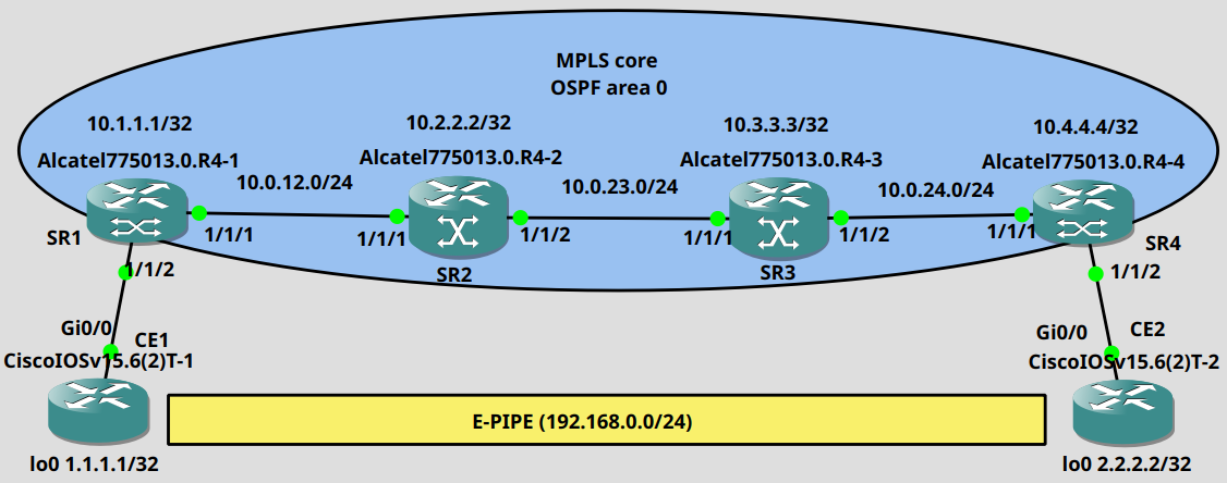
SR1 and SR4 are going to be the PE (LER) routers in this topology. I have already enabled OSPF globally in the core and advertised every physical as well as every system address (10.x.x.x/32). This is how the routing table looks like on SR1:
*A:SR1>config>router>ospf>area$ show router route-table ===============================================================================Route Table (Router: Base)===============================================================================Dest Prefix[Flags] Type Proto Age Pref Next Hop[Interface Name] Metric -------------------------------------------------------------------------------10.0.12.0/24 Local Local 00h06m11s 0 to_SR2 010.0.23.0/24 Remote OSPF 00h02m05s 10 10.0.12.2 20010.0.34.0/24 Remote OSPF 00h00m21s 10 10.0.12.2 30010.1.1.1/32 Local Local 00h06m28s 0 system 010.2.2.2/32 Remote OSPF 00h04m04s 10 10.0.12.2 10010.3.3.3/32 Remote OSPF 00h02m00s 10 10.0.12.2 20010.4.4.4/32 Remote OSPF 00h00m15s 10 10.0.12.2 300-------------------------------------------------------------------------------No. of Routes: 7 Flags: n = Number of times nexthop is repeated B = BGP backup route available L = LFA nexthop available S = Sticky ECMP requested ===============================================================================
We need to configure the customer facing ports (1/1/2 on both PEs) as access ports to be able to apply a SAP to the ports later:
*A:SR1>config# port 1/1/2 *A:SR1>config>port# ethernet mode access *A:SR1>config>port# no shutdown *A:SR1>config>port# back
Next we enable LDP in the core on the physical interfaces. This is how we do it on SR2 for example:
*A:SR2>config>router# ldp *A:SR2>config>router>ldp$ interface-parameters *A:SR2>config>router>ldp>if-params$ interface "to_SR1" *A:SR2>config>router>ldp>if-params>if$ back *A:SR2>config>router>ldp>if-params$ interface "to_SR3" *A:SR2>config>router>ldp>if-params>if$ back *A:SR2>config>router>ldp>if-params$ back *A:SR2>config>router>ldp$ no shutdown
Make sure that every router advertises its system address via OSPF: the LDP session is built between the system IP addresses. If the neighboring routers cannot establish the TCP session they won't be able to exchange labels.
We can verify that the LSP (Label Switched Path) has been established between the two remote PEs using the following command:
*A:SR1>config>router>ldp$ oam lsp-ping prefix 10.4.4.4/32 LSP-PING 10.4.4.4/32: 80 bytes MPLS payloadSeq=1, send from intf to_SR2, reply from 10.4.4.4 udp-data-len=32 ttl=255 rtt=8.29ms rc=3 (EgressRtr)---- LSP 10.4.4.4/32 PING Statistics ----1 packets sent, 1 packets received, 0.00% packet lossround-trip min = 8.29ms, avg = 8.29ms, max = 8.29ms, stddev = 0.000ms
Next we create and SDP service on each PE and identify the remote PE with its system address as the far-end:
*A:SR1>config# service sdp 14 mpls create *A:SR1>config>service>sdp$ far-end 10.4.4.4 *A:SR1>config>service>sdp$ ldp *A:SR1>config>service>sdp$ no shutdown
*A:SR4>config# service sdp 14 mpls create *A:SR4>config>service>sdp$ far-end 10.1.1.1 *A:SR4>config>service>sdp$ ldp *A:SR4>config>service>sdp$ no shutdown
The SDP service ID is locally significant, it doesn't have to match on the PEs, it can be different. Using ldp it'll build a targeted LDP session between the two remote PE to distribute the service label information. Use this to verify that the targeted LDP session is established successfully:
*A:SR1>config>service# show router ldp session ==============================================================================LDP IPv4 Sessions==============================================================================Peer LDP Id Adj Type State Msg Sent Msg Recv Up Time------------------------------------------------------------------------------10.2.2.2:0 Link Established 295 297 0d 00:12:5710.4.4.4:0 Targeted Established 78 80 0d 00:06:37------------------------------------------------------------------------------No. of IPv4 Sessions: 2==============================================================================
Next we configure the epipe service on the PEs as the following:
*A:SR4>config# service epipe 100 customer 1 create *A:SR4>config>service>epipe$ sap 1/1/2 create *A:SR4>config>service>epipe>sap$ back *A:SR4>config>service>epipe$ spoke-sdp 14:100 create
*A:SR1>config# service epipe 100 customer 1 create *A:SR1>config>service>epipe$ sap 1/1/2 create *A:SR1>config>service>epipe>sap$ back *A:SR1>config>service>epipe$ spoke-sdp 14:100 create
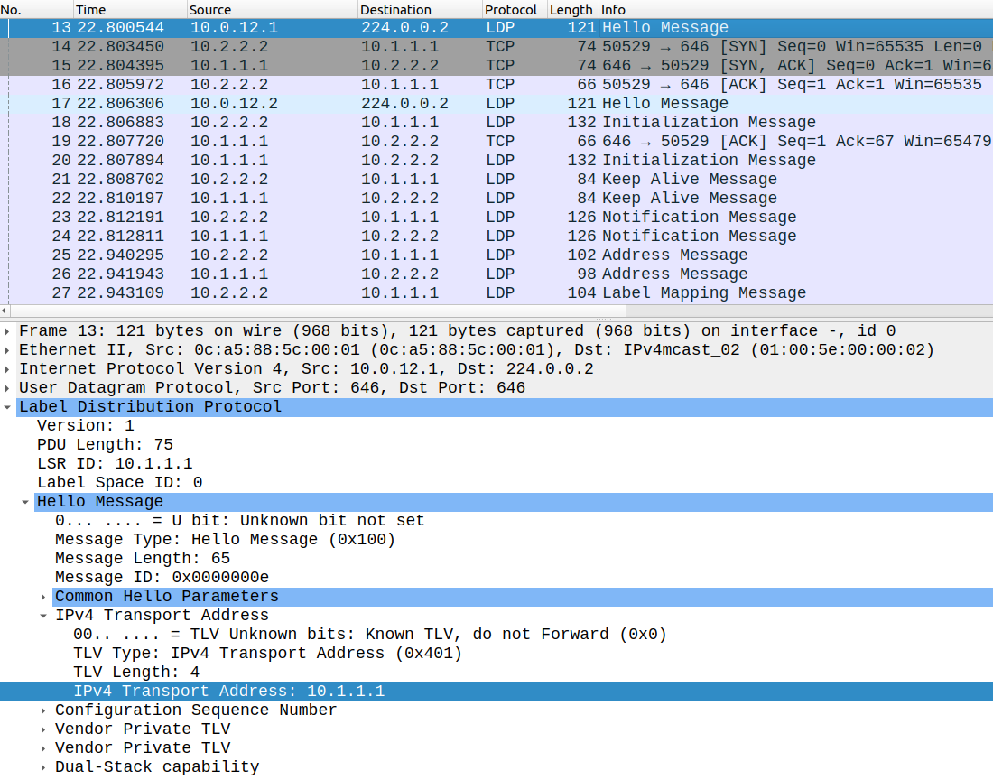
We assign the sap to the customer facing access port, and we assign the sdp to the epipe service using the commands above. By issuing these commands a Label Mapping Message has been exchanged between the two remote PEs using the targeted LDP session which looks like this:
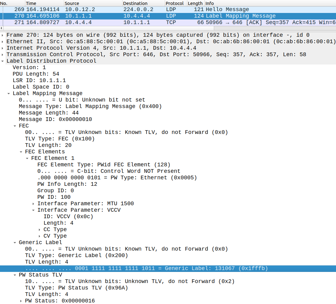
Here the epipe service id is transferred as the PW ID which has to match with the remote PE, and the MTU is set to 1500 bytes by default. We also exchange the service label (131067) with the the other PE. This will be used as the inner label when we verify the data-plane later in the MPLS cloud. We can also use this command:
*A:SR1>config>service# show service id 100 labels ===============================================================================Martini Service Labels===============================================================================Svc Id Sdp Binding Type I.Lbl E.Lbl-------------------------------------------------------------------------------100 14:100 Spok 131067 131067-------------------------------------------------------------------------------Number of Bound SDPs : 1-------------------------------------------------------------------------------===============================================================================
Now let's verify the data-plane and establish an OSPF adjacency with the IOSv routers:
CE1(config)#int lo0CE1(config-if)#ip address 1.1.1.1 255.255.255.255CE1(config-if)#ip ospf 1 area 0 CE1(config-if)#exitCE1(config)#int g0/0CE1(config-if)#ip addr 192.168.0.1 255.255.255.0CE1(config-if)#ip ospf 1 area 0CE1(config-if)#no shut*Jul 22 17:39:02.077: %OSPF-5-ADJCHG: Process 1, Nbr 2.2.2.2 on GigabitEthernet0/0 from LOADING to FULL, Loading Done
The configuration of CE2 is basically the mirror image of CE1, I just changed the addresses. And the two routers have successfully become adjacent:
CE1#show ip ospf neighbor Neighbor ID Pri State Dead Time Address Interface2.2.2.2 1 FULL/BDR 00:00:33 192.168.0.2 GigabitEthernet0/0
If we run a traceroute the MPLS core is of course hidden from the customer:
CE1#traceroute 2.2.2.2 numeric Type escape sequence to abort.Tracing the route to 2.2.2.2VRF info: (vrf in name/id, vrf out name/id) 1 192.168.0.2 6 msec 4 msec 4 msec
From the customer's perspective it looks like as the two devices were directly back to back connected. We can also verify the MTU on the customer side: it is set by default to 1500 bytes:
CE1#ping 2.2.2.2 size 1500 df-bit Type escape sequence to abort.Sending 5, 1500-byte ICMP Echos to 2.2.2.2, timeout is 2 seconds:Packet sent with the DF bit set!!!!!Success rate is 100 percent (5/5), round-trip min/avg/max = 2/3/6 msCE1#CE1#ping 2.2.2.2 size 1501 df-bit Type escape sequence to abort.Sending 5, 1501-byte ICMP Echos to 2.2.2.2, timeout is 2 seconds:Packet sent with the DF bit set.....Success rate is 0 percent (0/5)
The MPLS label stack in the core looks like this: similarly to the L3VPNs we have two labels:
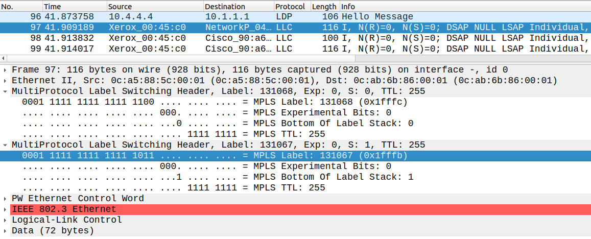
The inner label (131067) identifies the service, this is what has been transferred via the targeted LDP session, and the outer transport label (131068) identifies the remote PE according to the LDP bindings table. On SR1 it looks like this:
*A:SR1>config>service# show router ldp bindings active ===============================================================================LDP Bindings (IPv4 LSR ID 10.1.1.1:0) (IPv6 LSR ID ::[0])===============================================================================Legend: U - Label In Use, N - Label Not In Use, W - Label Withdrawn WP - Label Withdraw Pending, BU - Alternate For Fast Re-Route (S) - Static (M) - Multi-homed Secondary Support (B) - BGP Next Hop (BU) - Alternate Next-hop for Fast Re-Route (C) - FEC resolved for class-based-forwarding===============================================================================LDP IPv4 Prefix Bindings (Active)===============================================================================Prefix Op IngLbl EgrLblEgrNextHop EgrIf/LspId -------------------------------------------------------------------------------10.1.1.1/32 Pop 131071 -- -- -- 10.2.2.2/32 Push -- 13107110.0.12.2 1/1/1 10.3.3.3/32 Push -- 13106910.0.12.2 1/1/1 10.3.3.3/32 Swap 131069 13106910.0.12.2 1/1/1 10.4.4.4/32 Push -- 13106810.0.12.2 1/1/1 10.4.4.4/32 Swap 131068 13106810.0.12.2 1/1/1 -------------------------------------------------------------------------------No. of IPv4 Prefix Active Bindings: 6 ===============================================================================
For example if SR1 sends the packet destined to SR4 it inserts the label of 131068 to the IP packet. Finally to verify or troubleshoot the epipe service use the following command:
*A:SR1>config>service# oam svc-ping 10.4.4.4 service 100 Service-ID: 100Err Info Local Remote----------------------------------------------------- Type: EPIPE EPIPE Admin State: Up Up ==> Oper State: Down Down Service-MTU: 1514 1514 Customer ID: 1 1 IP Interface State: Up Actual IP Addr: 10.1.1.1 10.4.4.4 Expected Peer IP: 10.4.4.4 10.1.1.1 SDP Path Used: No No SDP-ID: 14 14 Admin State: Up Up Operative State: Up Up Binding Admin State:Up Up Binding Oper State: Up Up Binding VC ID: 100 100 Binding Type: Spoke Spoke Binding Vc-type: Ether Ether Binding Vlan-vc-tag:N/A N/A Egress Label: 131067 131067 Ingress Label: 131067 131067 Egress Label Type: Signaled Signaled Ingress Label Type: Signaled Signaled Request Result: Send - Reply Received: Original Service ID Oper-Down
The ping should be destined to the remote PE, here I shut down PE facing interfaces on the CE devices on purpose, that's the reason why it shows it as "Oper-Down".