Implementing MPLS-TE: VPN over the TE tunnel from PE to PE, TE metric, explicit-path
By default the IGP metric (ISIS/OSPF cost) determines how the packets are forwarded within the MPLS core. With MPLS Traffic Engineering (TE) we can be much more granular: TE is used to manually or dynamically determine the LSPs (Label Switched Path) based on criteria other than the IGP metric. This can be the required bandwidth, link affinity ("coloring") or we can even manually specify the LSP: we can determine each hop within the MPLS core the packets should take beforehand.
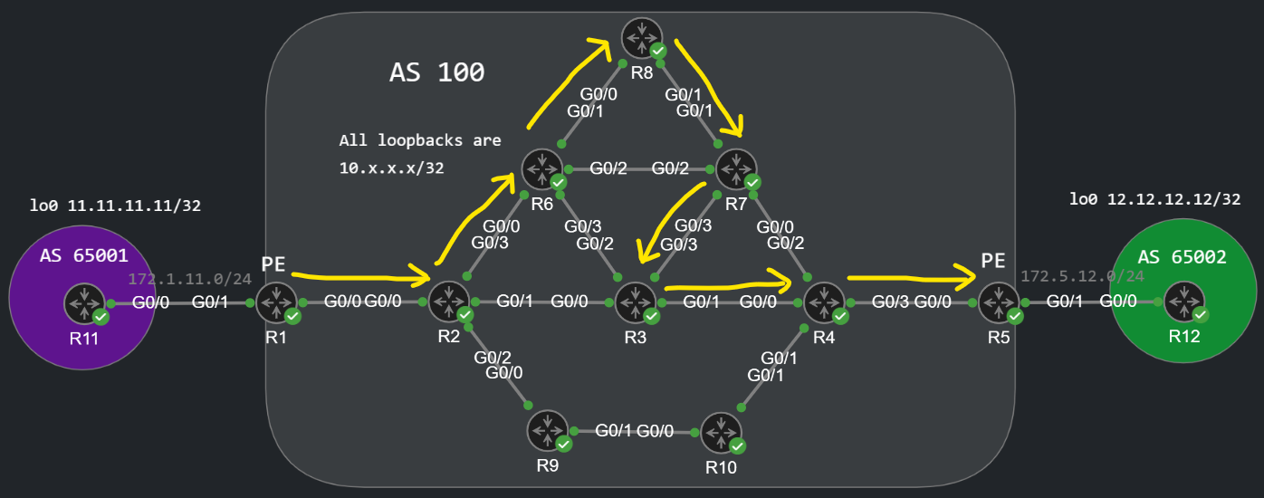
In this example we're going to use RSVP-TE as the control plane for signaling. RSVP-TE is basically RSVP which was meant to be used for IntServ QoS, but with with TE extensions. Alternatively we can also use Segment Routing for traffic engineering (SR-TE). MPLS-TE in general is a very large topic, in this post we're going take a look at just some basic examples how it works. This is the topology we're going to work with in this lab:
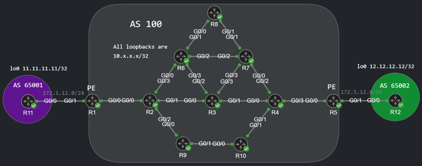
We have an L3VPN service between AS 65001 and AS 65002, but that's not the point here, we can have any kind of MPLS VPN service between the CE and the PE routers. The point is how the traffic is forwarded between the PE routers. By default we take the following path if the OSPF cost of all links are equal: R1 -> R2 -> R3 -> R4 -> R5:
R11#traceroute 12.12.12.12 so lo0 numType escape sequence to abort.Tracing the route to 12.12.12.12VRF info: (vrf in name/id, vrf out name/id) 1 172.1.11.1 1 msec 2 msec 1 msec 2 10.0.12.2 [MPLS: Labels 2012/5022 Exp 0] 5 msec 6 msec 7 msec 3 10.0.23.3 [MPLS: Labels 3012/5022 Exp 0] 5 msec 6 msec 6 msec 4 10.0.34.4 [MPLS: Labels 4012/5022 Exp 0] 5 msec 5 msec 6 msec 5 172.5.12.5 [MPLS: Label 5022 Exp 0] 5 msec 4 msec 5 msec 6 172.5.12.12 6 msec * 3 msec
I assigned custom label range to all of the routers in the core. R1 creates labels between 1000 and 1999, R2 between 2000 and 2999 etc., so we can easily determine the path the packets take within the MPLS core just by looking at the traceroute. We could change the OSPF cost on the interfaces in the core of course to influence the path selection, but that would affect other things as well not just the LSP between R1 and R5.
Enable MPLS-TE and RSVP-TE
So let's enable TE globally and on the interfaces within the core with the following commands:
R2(config)#mpls traffic-eng tunnelsR2(config)#router ospf 1R2(config-router)#mpls traffic-eng area 0R2(config-router)#mpls traffic-eng router-id lo0R2(config-router)#int range g0/0 - 3R2(config-if-range)#mpls traffic-eng tunnelsR2(config-if-range)#ip rsvp bandwidth
We need to issue these commands on all of the routers in the core. RSVP only needs to be enabled on the interfaces within the core, we don't enable RSVP on the interfaces towards the customer of course. For verification we can issue the following command:
R2#show mpls interfacesInterface IP Tunnel BGP Static OperationalGigabitEthernet0/0 Yes (ldp) Yes No No Yes GigabitEthernet0/1 Yes (ldp) Yes No No Yes GigabitEthernet0/2 Yes (ldp) Yes No No Yes GigabitEthernet0/3 Yes (ldp) Yes No No Yes
The IP column means that we run LDP on the interface (mpls ldp autoconfig under OSPF for example), the Tunnel column indicates that MPLS-TE has been enabled. Remember that LDP is an IGP-based label distribution method, RSVP-TE which also provides labels, is whole different and separate thing, RSVP-TE doesn't require LDP at all. LDP provides labels for prefixes in the RIB, RSVP reserves labels for the tunnel/LSP (in this case between the two PEs). If we just wanted to establish reachability between the two PEs (R1 and R5), we wouldn't need LDP at all, because RSVP could also signal the label information to the whole network. To make sure that RSVP is enabled on all of the interfaces in the core we can run the following command for verification:
R2#show ip rsvp interface interface rsvp allocated i/f max flow max sub max VRFGi0/0 ena 0 750M 750M 0 Gi0/1 ena 0 750M 750M 0 Gi0/2 ena 0 750M 750M 0 Gi0/3 ena 0 750M 750M 0
Notice that by default the ip rsvp bandwidth command sets the maximum reservable bandwidth to 75% of the interface bandwidth (we have 1 Gbps interfaces everywhere, so that's 750 Mbps). We can specify other values if we want, but we need this command on the interfaces to enable RSVP.
About the OSPF Underlay
For MPLS-TE we need a link-state IGP because the routers need visibility to the whole network. So practically we run OSPF or ISIS in the core. Distance Vector protocols like RIP or EIGRP are not very flexible for TE. In this example we use OSPF in the MPLS core, furthermore everything is in area 0, so every router has the same LSDB, and has the same information about the topology in the core. Inter-area TE tunnels are also possible, but in this post we'll just examine one of the easiest option: an intra-area TE tunnel between the two PE routers. The moment we issue these commands under the OSPF process, the routers start creating Type-10 Opaque LSAs and flood them within the backbone area. The routers use this LSA to send MPLS-TE information to each other.
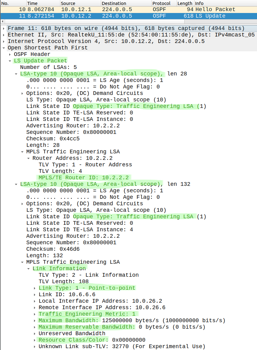
As you can see these Type-10 LSAs have a lot of information: max. reservable bandwidth, TE metric (which is the IGP metric by default), link affinity (color) etc. The first LSA describes the advertising router itself (10.2.2.2), the second LSA describes one of his links. Notice that this is just one link, this LSU has many more link information, I just cut down the rest of it. To view all of the Type-10 LSAs in the LSDB you can issue the following command:
R1#show ip ospf database opaque-area
The output of this show command will be very extensive since we have a many routers and links in this topology, so I won't paste that in here.
Creating the TE tunnel interface
Next we create a tunnel interface on the headend (R1) router. Notice that the TE tunnels are unidirectional (from headend [R1] to tailend [R5]) just like the IPsec SAs, if R1 forwards the packets through the tunnel interface that doesn't mean that R5 forwards the packets on the same path in the reverse direction.
R1(config)#int tun 1R1(config-if)#ip unnumbered lo0R1(config-if)#tunnel destination 10.5.5.5R1(config-if)#tunnel mode mpls traffic-eng R1(config-if)#tunnel mpls traffic-eng path-option 1 dynamic
Notice that there's no tunnel source, with the ip unnumbered loopback0 command we don't specify an IP address explicitly for this tunnel interface as a source, but we say that the tunnel should use the IP address of the loopback0 interface. We also need to specify the tunnel mode (tunnel mode mpls traffic-eng), because the default tunnel mode is GRE. The tunnel destination is the loopback of R5, the other PE router. Optionally we could also specify the required bandwidth for this tunnel with the following command: tunnel mpls traffic-eng bandwidth <bw. in kbps>. With the last command we tell the router to use CSPF (Constrained Shortest Path First, which is normal SPF but supplemented with the TE parameters aka. "constraints") to dynamically calculate the best path based on the underlying OSPF topology using the TE constraints.
Basic RSVP-TE operation - PATH and RESV messages
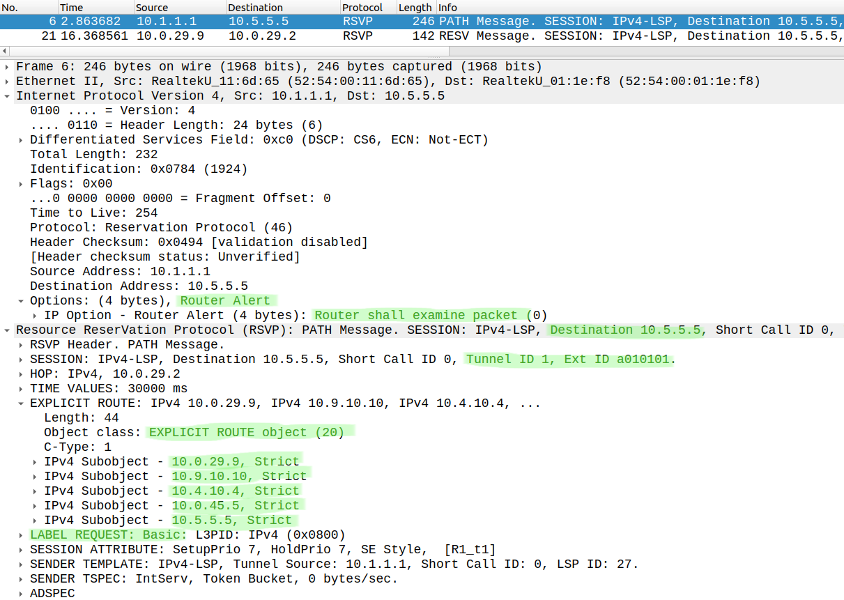
After issuing these commands above, the headend router sends an RSVP PATH message to the tailend router:
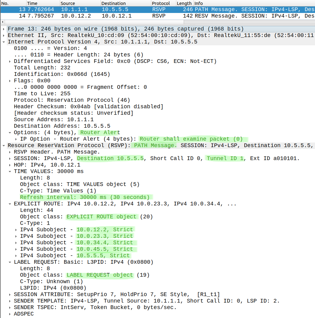
The purpose of this message is to request the reservation of the resources (those configured on the tunnel interface) from every router along the path. For example we can request a bandwidth reservation if we've configured the tunnel mpls traffic-eng bandwidthcommand on the tunnel interface. As a result the routers subtract the required bandwidth from the max. reservable bandwidth configured on the physical interfaces. This message is also used to request an MPLS label for the TE tunnel. Notice that this packet has the Router Alert IP Option which instruct the routers along the path between R1 and R5 to perform deeper inspection of this IP packet. So these packets won't be just forwarded on the data plane like any other data packet, these packets will be software-switched and sent to the CPU of each router along the path. Besides that there are plenty of information in the RSVP PATH: we can see the tunnel ID (1), the refresh interval, which is 30 seconds by default, so these RSVP messages will be resent every 30 seconds. We can see that R1 requests label information for the TE tunnel, the ERO (Explicit Route Object) is also included here: this is a sequence of IP addresses (next-hop routers) between the tunnel endpoints. This is always calculated by the headend router based on the modified Dijkstra algorithm (CSPF), and result is the ERO. By default the headend router uses the TE metric (or administrative weight) to calculate the best path, and the TE metric equals to the IGP metric by default. Regular traffic will still use the IGP metric (OSPF cost). Alternatively with the following command, which we can issue under the tunnel interface, we can choose to use the underlying OSPF metric if we want (igp) or we stick to the TE metric which is the default (te) to select the best path:
tunnel mpls traffic-eng path-selection metric igp|te
So the result is the same path as the IGP best path: R1 -> R2 -> R3 -> R4 -> R5 in this case.
As a response the tailend router generates an RSVP RESV message as a confirmation that the requested reservation can be achieved, and he sends it towards the headend router:
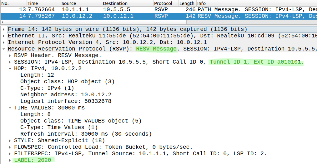
This message is actually sent router-by-router: R5 sends to R4, R4 generates an RESV for R3, R3 generates a new one and sends to R2 etc... Above we can see the RSVP RESV message sent by R2 to R1. This message also has a lot of information, I just highlighted the most important: this message carries the label information. R1 should use MPLS label 2020 when he sends traffic though the TE tunnel to R2. We can also see the Tunnel ID (1), notice that we can have multiple TE tunnels, they can also preempt each other based on the Setup and Hold priorities which are present in the previous RSVP PATH message above.
Sending traffic through the TE tunnel
Once the TE tunnel is up, it won't do anything by default: the TE tunnel interface won't be used automatically, we have route traffic into the tunnel. We have several options: static routing pointing to the tunnel interface, dynamic routing (autoroute announce) or PBR where we set the interface in the route-map to tunnel 1 (set interface tunnel 1). The most appropriate solution is the second (dynamic) option where we issue the following command under the tunnel interface:
R1(config-if)#tunnel mpls traffic-eng autoroute announce
This command enables the TE tunnel to take part in the underlying IGP: we modify the SPF algorithm by adding the TE tunnel interfaces to the SPF tree. The result is that any network which can be found behind the tailend router of the TE tunnel will be included in the RIB with the next-hop of the tunnel 1 interface. Basically any destination reachable via R5 will now be available though the tunnel 1 interface. It's important to note that R1 does NOT readvertises these routes to other OSPF neighbors, this change is only local to the RIB of R1. So after issuing the command above, the loopback of R5 is now reachable through the tunnel 1 interface:
R1#show ip route 10.5.5.5Routing entry for 10.5.5.5/32 Known via "ospf 1", distance 110, metric 5, type intra area Last update from 10.5.5.5 on Tunnel1, 00:00:14 ago Routing Descriptor Blocks: * 10.5.5.5, from 10.5.5.5, 00:00:14 ago, via Tunnel1 Route metric is 5, traffic share count is 1
Alternatively I could also configure a static route for this destination like this:
R1(config)#ip route 10.5.5.5 255.255.255.255 tunnel 1
This would also work, but notice that static routing is not scalable, so we usually just choose the dynamic option and work with the autoroute announce.
Constraint-based Path Computation and TE metric
Now that we can send traffic though the TE tunnel, let's take a look at how the CSPF and the TE parameters (also known as constraints) work which I've already mentioned briefly above. Right now we have no constraints (like reserved bandwidth for example), so CSPF will choose the path based on the lowest TE metric. The TE metric is by default equals to the IGP metric. So the TE metric (path weight in the output below) to reach R5 is 4 at the moment (with default OSPF settings every interface has a cost of 1). For verification we can run the following:
R1#show mpls traffic-eng tunnels Name: R1_t1 (Tunnel1) Destination: 10.5.5.5 Status: Admin: up Oper: up Path: valid Signalling: connected path option 1, type dynamic (Basis for Setup, path weight 4) Config Parameters: Bandwidth: 0 kbps (Global) Priority: 7 7 Affinity: 0x0/0xFFFF Metric Type: TE (default) AutoRoute: enabled LockDown: disabled Loadshare: 0 bw-based auto-bw: disabled Active Path Option Parameters: State: dynamic path option 1 is active BandwidthOverride: disabled LockDown: disabled Verbatim: disabled InLabel : - OutLabel : GigabitEthernet0/0, 2020 RSVP Signalling Info: Src 10.1.1.1, Dst 10.5.5.5, Tun_Id 1, Tun_Instance 2 RSVP Path Info: My Address: 10.0.12.1 Explicit Route: 10.0.12.2 10.0.23.3 10.0.34.4 10.0.45.5 10.5.5.5 Record Route: NONE Tspec: ave rate=0 kbits, burst=1000 bytes, peak rate=0 kbits RSVP Resv Info: Record Route: NONE Fspec: ave rate=0 kbits, burst=1000 bytes, peak rate=0 kbits History: Tunnel: Time since created: 7 minutes, 27 seconds Time since path change: 5 minutes, 56 seconds Number of LSP IDs (Tun_Instances) used: 2 Current LSP: Uptime: 5 minutes, 56 seconds Prior LSP: ID: path option 1 [1] Removal Trigger: tunnel shutdown
This command also provides a lot of information regarding the TE tunnel, I just highlighted the ones which are the most important for us right now. At this point the TE tunnel should be up and Signalling should show connected. We can see that I haven't specified any bandwidth requirements for this tunnel as constraints, path-option 1 dynamic is active which basically just means that the TE metric is used to select the best path. The result of the CSPF calculation is the Explicit Route (ERO): these are the IP addresses of the routers along the LSP which we use to forward the packets. We can also see the label information (2020) which we've already seen in the RSVP RESV message above.
Now let's increase the TE metric on the interface G0/1 and G0/3 to influence path selection:
R2(config)#int range g0/1, g0/3R2(config-if-range)#mpls traffic-eng administrative-weight 10
We basically want to avoid the paths towards R3 and R6, now we should take the path R1 -> R2 -> R9 -> R10 -> R4 -> R5. Notice that the IGP path is still the same, the OSPF cost on the interfaces is unchanged, what we've changed is only the LSP for this TE tunnel. Let's do a manual reoptimization on the headend:
R1#mpls traffic-eng reoptimize
By default the routes do the reoptimization about every hour periodically, but we can also force them manually with the command above (we usually run this always after we change something to verify the result right away). Now if R11 runs a traceroute towards the loopback of R12, we should take a different path:
R11#trace 12.12.12.12 so lo0 numType escape sequence to abort.Tracing the route to 12.12.12.12VRF info: (vrf in name/id, vrf out name/id) 1 172.1.11.1 2 msec 2 msec 2 msec 2 10.0.12.2 [MPLS: Labels 2019/5022 Exp 0] 5 msec 4 msec 5 msec 3 10.0.29.9 [MPLS: Labels 9021/5022 Exp 0] 5 msec 4 msec 5 msec 4 10.9.10.10 [MPLS: Labels 10021/5022 Exp 0] 5 msec 5 msec 5 msec 5 10.4.10.4 [MPLS: Labels 4019/5022 Exp 0] 5 msec 4 msec 5 msec 6 172.5.12.5 [MPLS: Label 5022 Exp 0] 5 msec 5 msec 4 msec 7 172.5.12.12 5 msec * 4 msec
That's the same path we predicted above. Let's change back the TE metrics to their default value:
R2(config)#int range g0/1, g0/3R2(config-if-range)#no mpls traffic-eng administrative-weight 10
Creating an Explicit Path
So far we've used the path-option 1 dynamic which means that the tunnel will use the TE metric. Besides the TE metric, the TE constraints can be manipulated in a lot of ways. One of them is the explicit-path. With the explicit path option we can define the interfaces or the routers which we should use or avoid. For example let's say we want to take the following path between the PEs:
In this example we're going to include the RID of the routers we want the LSP to pass through, so this is how we can create the explicit-path:
R1(config)#do show run | sec explicitip explicit-path name R1_TO_R5 enable next-address 10.2.2.2 next-address 10.6.6.6 next-address 10.8.8.8 next-address 10.7.7.7 next-address 10.3.3.3 next-address 10.4.4.4 next-address 10.5.5.5
We basically just list the RIDs one-by-one, next we need to apply this explicit-path to the tunnel interface itself:
R1(config)#int tun 1R1(config-if)#tunnel mpls traffic-eng path-option 1 explicit name R1_TO_R5R1(config-if)#tunnel mpls traffic-eng path-option 2 dynamic
Now path-option 1 is the explicit-path we've just created above, optionally we can also create additional path options. Here, if for some reason R1 can't take the path specified in path-option 1, it falls back to path-option 2 dynamic, and just use the TE metrics to choose the path. Before we verify what we've done let's do a reoptimization:
R1#mpls traffic-eng reoptimize
And we run a traceroute from R11 to the loopback of R12:
R11#trace 12.12.12.12 so lo0 numType escape sequence to abort.Tracing the route to 12.12.12.12VRF info: (vrf in name/id, vrf out name/id) 1 172.1.11.1 2 msec 1 msec 2 msec 2 10.0.12.2 [MPLS: Labels 2019/5022 Exp 0] 6 msec 6 msec 7 msec 3 10.0.26.6 [MPLS: Labels 6019/5022 Exp 0] 6 msec 5 msec 7 msec 4 10.0.68.8 [MPLS: Labels 8021/5022 Exp 0] 6 msec 6 msec 6 msec 5 10.0.78.7 [MPLS: Labels 7019/5022 Exp 0] 6 msec 6 msec 5 msec 6 10.0.37.3 [MPLS: Labels 3020/5022 Exp 0] 7 msec 6 msec 6 msec 7 10.0.34.4 [MPLS: Labels 4019/5022 Exp 0] 5 msec 5 msec 7 msec 8 172.5.12.5 [MPLS: Label 5022 Exp 0] 5 msec 7 msec 5 msec 9 172.5.12.12 6 msec * 6 msec
Based on the transport (outer) label information we can confirm that we use the LSP I just drew in the picture above.
Now let's create another explicit-path, but this time we'll do it differently with the exclude option. Our goal is now the following: we want exclude two nodes: R6 and R3, we don't want the LSP to go through these routers, basically we want the following:
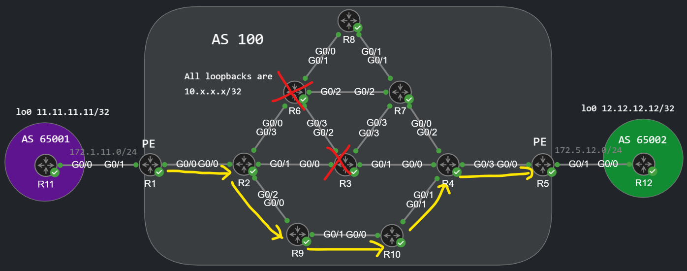
This effectively means that the LSP would go through the following routers: R1 -> R2 -> R9 -> R10 -> R4 -> R5. We configure the explicit-path as the following:
ip explicit-path name EXCLUDE_R3_R6 enable exclude-address 10.6.6.6 exclude-address 10.3.3.3
And apply the explicit-path to the tunnel interface:
R1(config)#int tun 1R1(config-if)# tunnel mpls traffic-eng path-option 1 explicit name EXCLUDE_R3_R6R1#mpls traffic-eng reoptimize
R1 sends the following RSVP PATH message with the ERO we've just anticipated above:
Let's run the same traceroute again:
R11#traceroute 12.12.12.12 so lo0 numType escape sequence to abort.Tracing the route to 12.12.12.12VRF info: (vrf in name/id, vrf out name/id) 1 172.1.11.1 2 msec 2 msec 2 msec 2 10.0.12.2 [MPLS: Labels 2021/5022 Exp 0] 24 msec 6 msec 5 msec 3 10.0.29.9 [MPLS: Labels 9021/5022 Exp 0] 6 msec 5 msec 5 msec 4 10.9.10.10 [MPLS: Labels 10021/5022 Exp 0] 6 msec 5 msec 5 msec 5 10.4.10.4 [MPLS: Labels 4021/5022 Exp 0] 6 msec 5 msec 5 msec 6 172.5.12.5 [MPLS: Label 5022 Exp 0] 4 msec 5 msec 5 msec 7 172.5.12.12 4 msec * 4 msec
We can confirm that the packets take the path we've just predicted above.
Finally let's run some show commands and verify the operation of the TE tunnel from the perspective of a midpoint router, R2 for example. Remember that the RSVP doesn't just operate on the headend and tailend router like BGP does for example, every router in the middle needs to be aware of the tunnel and have ingress/egress MPLS labels assigned for the tunnel. Here is what we can see on R2:
R2#show mpls traffic-eng tunnels LSP Tunnel R1_t1 is signalled, connection is up InLabel : GigabitEthernet0/0, 2021 OutLabel : GigabitEthernet0/2, 9021 RSVP Signalling Info: Src 10.1.1.1, Dst 10.5.5.5, Tun_Id 1, Tun_Instance 27 RSVP Path Info: My Address: 10.0.29.2 Explicit Route: 10.0.29.9 10.9.10.10 10.4.10.4 10.0.45.5 10.5.5.5 Record Route: NONE Tspec: ave rate=0 kbits, burst=1000 bytes, peak rate=0 kbits RSVP Resv Info: Record Route: NONE Fspec: ave rate=0 kbits, burst=1000 bytes, peak rate=0 kbits
R1_t1 identifies the tunnel we've created on R1, we can see the ERO from the perspective of R2, and also the ingress/egress label information, which we can also see in the LFIB:
R2#show mpls forwarding-table Local Outgoing Prefix Bytes Label Outgoing Next Hop Label Label or Tunnel Id Switched interface <omitted>2021 9021 10.1.1.1 1 [27] 6636 Gi0/2 10.0.29.9
Normally we used to have prefixes in the in the third column, because LDP sends the label information for prefixes. Now we have the tunnel ID here, RSVP sends label information for the TE tunnel itself. Nevertheless we have the same inbound (2021) and outgoing (9021) labels as above. Here is the RSVP RESV message which was sent by R9 to R2:
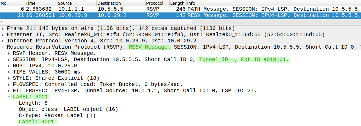
Here we can see the same label information (9021), R2 uses this transport label when it sends the traffic to R9. The main takeaway is that instead of LDP, RSVP provides the label information for the TE tunnel.
And finally one last thing which I've already mentioned briefly above: remember that TE tunnel are UNIdirectional, the return traffic still must use the OSPF underlay to get back to R1:
R12#traceroute 11.11.11.11 so lo0 numeric Type escape sequence to abort.Tracing the route to 11.11.11.11VRF info: (vrf in name/id, vrf out name/id) 1 172.5.12.5 1 msec 1 msec 2 msec 2 10.0.45.4 [MPLS: Labels 4002/1022 Exp 0] 6 msec 5 msec 5 msec 3 10.0.34.3 [MPLS: Labels 3001/1022 Exp 0] 5 msec 4 msec 5 msec 4 10.0.23.2 [MPLS: Labels 2000/1022 Exp 0] 5 msec 5 msec 4 msec 5 172.1.11.1 [MPLS: Label 1022 Exp 0] 5 msec 4 msec 5 msec 6 172.1.11.11 6 msec * 4 msec
So as we can see above: if I run a traceroute from R12 to R11, we simply follow the IGP best path which is R5 -> R4 -> R3 -> R2 -> R1.