Multicast over MPLS: mVPN Profile 0 (Draft Rosen)
Previously I wrote a few posts about how multicast works but only within an enterprise environment without MPLS. This time we're going to take a look from the service provider's perspective how we can provide multicast services for customers besides L3VPN services. We're going to work with the following topology:
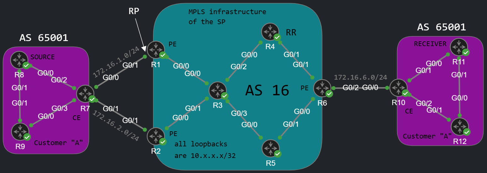
This time we're going to have only a single customer for the sake of the simplicity. This time we use BGP as the PE-CE routing protocol, but that is not really relevant here. The point is that customer "A" has unicast connectivity between his two sites, because I've already configured the L3VPN service. Besides that customer "A" has already enabled PIM on all interfaces of his routers. So at the starting point we have two separate "PIM islands" on the left and on the right side, and we want to send multicast traffic form R8 to R11. The question is how do we tunnel the multicast traffic through the MPLS cloud? We have many options which are called mVPN profiles. We have 30 profiles, but not all of them are supported on Cisco platforms. Basically we go through the following "decision tree", and pick one option from each category:
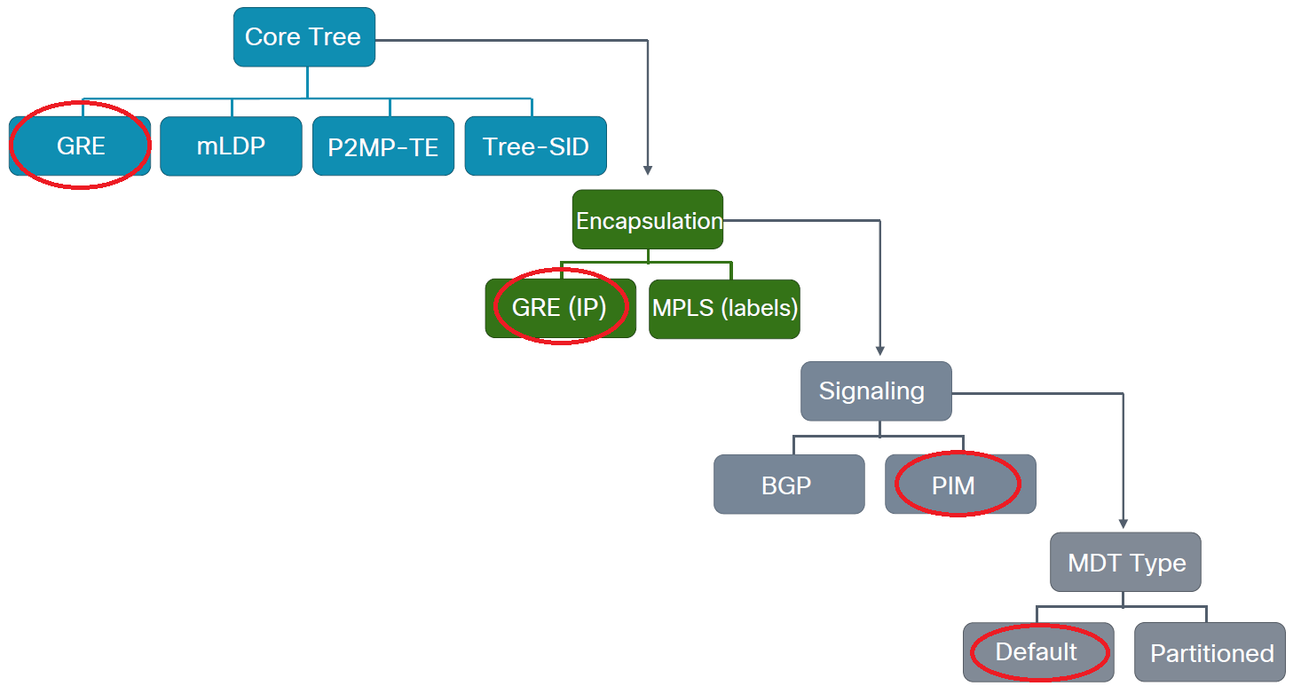
In this example we're going to configure one of the easiest solutions, Profile 0 which is called "Draft Rosen". In Profile 0 the service provider also runs PIM within the core and also on the VRF-aware, customer facing interfaces. So we have two separate PIM domains from the perspective of the service provider. And actually with this solution the multicast traffic traversing the MPLS core won't be MPLS encapsulated, so we won't have labels on the multicast packets. Instead we use GRE encapsulation between the PE routers, and the destination address of the GRE tunnel is going to be an SSM address which the PEs learn via BGP. This solution can be useful for compatibility issues, if a device doesn't support mLDP protocol which allows to encapsulate multicast traffic using MPLS labels. So we can decide whether we want to tunnel the multicast traffic inside GRE or with MPLS. We can also choose whether we want BGP or PIM for control-plane signaling in the core. We can also configure multicast for the customer with a PIM-free core! So let's take a look how we configure Profile 0 step-by-step.
Implementing Profile 0
First we enable multicast-routing in the core globally on every provider (LSR) router, and on the PE (LER) routers also for the customer VRFs:
R1(config)#ip multicast-routing vrf A R1(config)#ip multicast-routing
Next we build the PIM neighborships by enabling spare-mode on every interface. We don't want to have RPF issues, so simply enable PIM SM on every IGP (in my case OSPF) interface and also on the loopbacks of the PEs:
R1(config)#int g0/1R1(config-if)#ip pim sparse-mode R1(config-if)#int g0/0%PIM-5-DRCHG: VRF A: DR change from neighbor 0.0.0.0 to 172.16.1.1 on interface GigabitEthernet0/1R1(config-if)#int g0/0R1(config-if)#ip pim sparse-mode %PIM-5-DRCHG: DR change from neighbor 0.0.0.0 to 10.0.13.1 on interface GigabitEthernet0/0R1(config)#int lo0R1(config-if)#ip pim sparse-mode
So we build two separate multicast domains from the perspective of R1: one with the customer (G0/1 VRF interface) and one within the core (G0/0 interface in the global routing table). Next we have to choose a Rendezvous Point (RP) because we use PIM Sparse-Mode of course: it's recommended to choose a PE as the RP, so the RP should be within the service provider's infrastructure. This way we can limit how many and what specific sources can send multicast. So in this example I chose the g0/1 interface of R1. Notice that we cannot use the loopback here, because the loopback is in the global routing table, not in the VRF, the customers have no reachability to the loopback of R1, so we use the physical address. We use BSR to propagate the RP information:
R1(config)#ip pim vrf A bsr-candidate g0/1R1(config)#ip pim vrf A rp-candidate g0/1
The routers on the left side can learn the RP information without any problem:
R9#show ip pim rp mapping PIM Group-to-RP MappingsGroup(s) 224.0.0.0/4 RP 172.16.1.1 (?), v2 Info source: 172.16.1.1 (?), via bootstrap, priority 0, holdtime 150 Uptime: 00:05:09, expires: 00:02:17
But on the right side they obviously can't:
R10#show ip pim rp mapping PIM Group-to-RP Mappings
So our goal is to send the PIM messages through the MPLS cloud. In Profile 0 we have to establish a BGP neighborship between all of the PEs using the MDT (Multicast Distribution Tree) AFI and advertise a multicast membership associated with the VRF. In this example we use R4 as a Route Reflector (RR):
R1(config)#router bgp 16R1(config-router)#address-family ipv4 mdt R1(config-router-af)#neighbor 10.4.4.4 activate R2(config)#router bgp 16R2(config-router)#address-family ipv4 mdt R2(config-router-af)#neighbor 10.4.4.4 activate R6(config)#router bgp 16R6(config-router)#address-family ipv4 mdt R6(config-router-af)#neighbor 10.4.4.4 activate
I enabled the MDT AFI on all of the PEs, we also have to enable the MDT AFI on the RR as well, even if it's not a PE:
R4#show bgp all neighbors 10.1.1.1 | include Address family Address family IPv4 MDT: received Address family VPNv4 Unicast: advertised and received
The MDT capability is exchanged in the BGP OPEN messages, so we also have to advertise the capability on the RR, so we active the peers as RR-clients under the IPv4 MDT address-family:
R4(config)#router bgp 16R4(config-router)#address-family ipv4 mdtR4(config-router-af)#neighbor 10.1.1.1 activate R4(config-router-af)#neighbor 10.2.2.2 activate R4(config-router-af)#neighbor 10.6.6.6 activate R4(config-router-af)#neighbor 10.1.1.1 route-reflector-client R4(config-router-af)#neighbor 10.2.2.2 route-reflector-client R4(config-router-af)#neighbor 10.6.6.6 route-reflector-client
We should be able to establish the BGP neighborship, but as this point the PE routers don't advertise any NLRI:
R4#show bgp ipv4 mdt all summary BGP router identifier 10.4.4.4, local AS number 16BGP table version is 1, main routing table version 1Neighbor V AS MsgRcvd MsgSent TblVer InQ OutQ Up/Down State/PfxRcd10.1.1.1 4 16 8 20 1 0 0 00:01:41 010.2.2.2 4 16 8 16 1 0 0 00:01:33 010.6.6.6 4 16 8 13 1 0 0 00:01:21 0
For the multicast groups associated with the VRF we use source-specific multicast (SSM), which we have to enable globally on all routers on IOS and IOS-XE:
R1(config)#ip pim ssm default
And the membership is defined under the VRF on every PE:
R1(config)#vrf definition AR1(config-vrf)#address-family ipv4 unicast R1(config-vrf-af)#mdt default 232.0.0.1%PIM-5-NBRCHG: VRF A: neighbor 10.2.2.2 UP on interface Tunnel2 %PIM-5-DRCHG: VRF A: DR change from neighbor 10.1.1.1 to 10.2.2.2 on interface Tunnel2%PIM-5-NBRCHG: VRF A: neighbor 10.6.6.6 UP on interface Tunnel2 %PIM-5-DRCHG: VRF A: DR change from neighbor 10.2.2.2 to 10.6.6.6 on interface Tunnel2
In this example I use 232.0.0.1 SSM address, we have to specify the same address on all PEs. If the SSM addresses match the PEs become PIM adjacent in the customer VRF though a virtual tunnel interface as you can see above. So at this point we should have a PIM adjacency between all of the PEs in the VRF table:
R1#show ip pim vrf A neighbor PIM Neighbor TableMode: B - Bidir Capable, DR - Designated Router, N - Default DR Priority, P - Proxy Capable, S - State Refresh Capable, G - GenID Capable, L - DR Load-balancing CapableNeighbor Interface Uptime/Expires Ver DRAddress Prio/Mode172.16.1.7 GigabitEthernet0/1 00:47:49/00:01:40 v2 1 / DR S P G10.6.6.6 Tunnel2 00:01:33/00:01:42 v2 1 / DR S P G10.2.2.2 Tunnel2 00:01:45/00:01:40 v2 1 / S P G
This SSM group membership is what we advertise using the BGP MDT AFI, this is how a BGP UPDATE and the NLRI looks like:
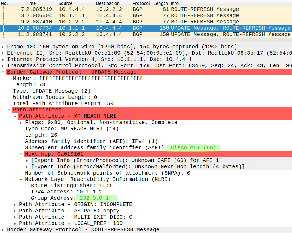
The Route Distinguishers (RD) don't have to match of course, just as with L3VPN. Wireshark couldn't decode the Next hop information here for some reason, but that's not a problem, the routers can. If we take a look at the mroute tables of the P routers within the MPLS core, we should have three (S,G) entries with the PE loopbacks as the source, since we use SSM. This is how the mroute table looks like on R3 for example:
R3#show ip mroute | section 232(10.1.1.1, 232.0.0.1), 00:02:43/00:02:55, flags: sT Incoming interface: GigabitEthernet0/0, RPF nbr 10.0.13.1 Outgoing interface list: GigabitEthernet0/3, Forward/Sparse, 00:02:31/00:02:55 GigabitEthernet0/1, Forward/Sparse, 00:02:43/00:02:44(10.6.6.6, 232.0.0.1), 00:02:57/00:03:26, flags: sT Incoming interface: GigabitEthernet0/3, RPF nbr 10.0.35.5 Outgoing interface list: GigabitEthernet0/1, Forward/Sparse, 00:02:43/00:02:43 GigabitEthernet0/0, Forward/Sparse, 00:02:57/00:03:26(10.2.2.2, 232.0.0.1), 00:02:57/00:03:28, flags: sT Incoming interface: GigabitEthernet0/1, RPF nbr 10.0.23.2 Outgoing interface list: GigabitEthernet0/3, Forward/Sparse, 00:02:31/00:02:58 GigabitEthernet0/0, Forward/Sparse, 00:02:57/00:03:28
Verification
At this point the routers on the right side should also be able to learn the RP's address though PIM. So now we have one single PIM domain from the customer's perspective, we've successfully connected the PIM "islands" of the customer through the MPLS cloud:
R10#show ip pim rp mapping PIM Group-to-RP MappingsGroup(s) 224.0.0.0/4 RP 172.16.1.1 (?), v2 Info source: 172.16.1.1 (?), via bootstrap, priority 0, holdtime 150 Uptime: 00:08:38, expires: 00:01:54
Now let's take a look at how the control plane and the data plane actually works. R11, the receiver joins a group by sending an IGMP Membership Report:
R11(config-if)#ip igmp join-group 239.0.0.1
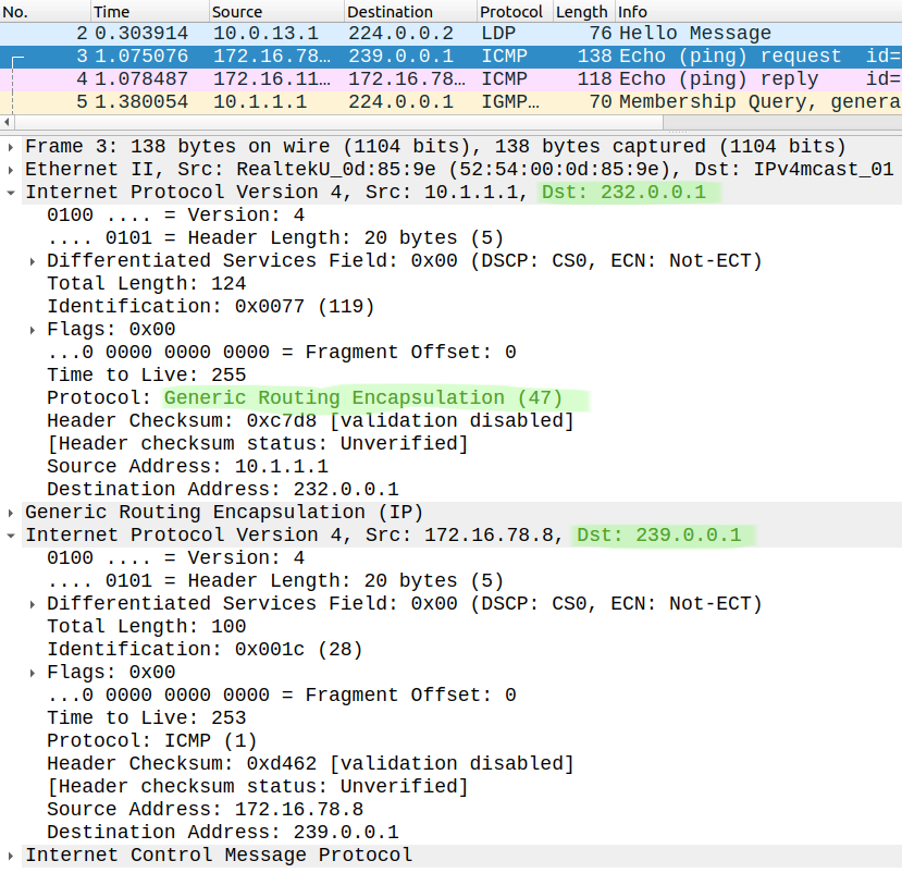
This creates a (*,G) entry in the mroute table of R10, and R10 sends a (*,G) PIM Join towards the RP, so he sends it to R6. R6 encapsulates the PIM Join message into GRE using the destination 232.0.0.1 SSM address. This is how the PIM Join message is forwarded within the MPLS infrastructure:
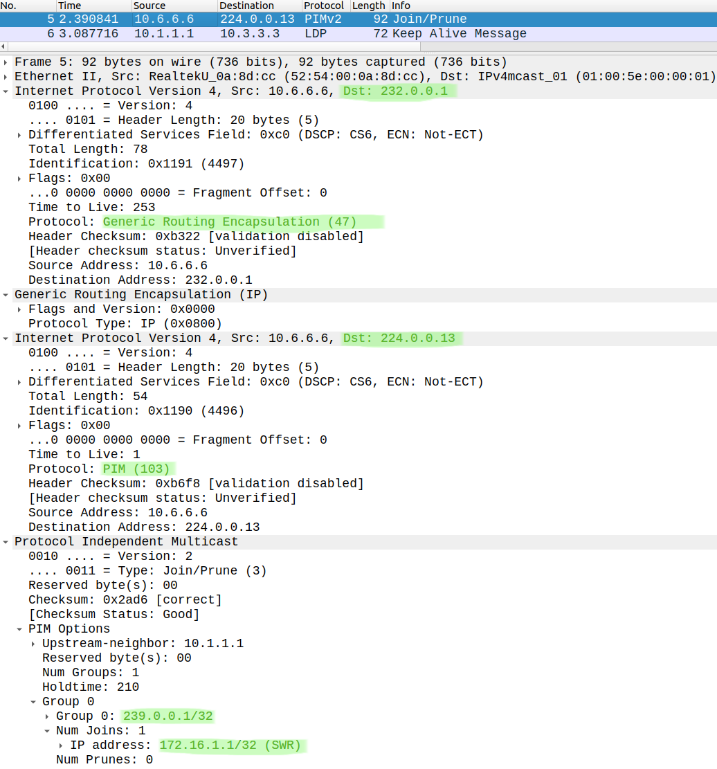
Notice that this packet is not MPLS encapsulated! This is an IP in IP encapsulation. The PIM message is encapsulated in GRE, and it is sent to the other two PEs which are listening to this 232.0.0.1 SSM address. Eventually it reaches the RP and creates a (*,G) entry in the mroute table:
R1#show ip mroute vrf A | sec 239(*, 239.0.0.1), 00:02:44/00:02:44, RP 172.16.1.1, flags: S Incoming interface: Null, RPF nbr 0.0.0.0 Outgoing interface list: Tunnel2, Forward/Sparse, 00:02:44/00:02:44
Notice that the OIL is the Tunnel2 virtual interface, this is the interface R1 has the PIM Join received on. Now the source (R8) starts sending the multicast stream:
R8#ping 239.0.0.1 rep 10 source gigabitEthernet 0/0Type escape sequence to abort.Sending 10, 100-byte ICMP Echos to 239.0.0.1, timeout is 2 seconds:Packet sent with a source address of 172.16.78.8 Reply to request 0 from 172.16.110.11, 7 msReply to request 1 from 172.16.110.11, 5 msReply to request 2 from 172.16.110.11, 5 msReply to request 3 from 172.16.110.11, 6 msReply to request 4 from 172.16.110.11, 6 ms...
It works, R11 sends back the ICMP Replies, also R1 the RP creates the (S,G) entry and adds the Tunnel2 interface to the OIL:
R1#show ip mroute vrf A | sec 239(*, 239.0.0.1), 00:11:48/00:02:33, RP 172.16.1.1, flags: S Incoming interface: Null, RPF nbr 0.0.0.0 Outgoing interface list: Tunnel2, Forward/Sparse, 00:11:48/00:02:33(172.16.78.8, 239.0.0.1), 00:07:37/00:01:39, flags: T Incoming interface: GigabitEthernet0/1, RPF nbr 172.16.1.7 Outgoing interface list: Tunnel2, Forward/Sparse, 00:07:37/00:02:45
Let's look at the data plane in the MPLS core:
We use exactly the same GRE encapsulation as with the PIM Join with the same multicast group address (232.0.0.1). Notice that every PE receives these multicast packets even if it doesn't have any receivers on the customer side (R2 for example in this topology). This is not necessarily efficient, and we can make some optimisation by defining a data mdt group: so we can use a separate group address for the control plane (PIM messages) and for the data plane messages. We issue the following command on each PE:
R1(config-vrf-af)#mdt data 232.16.16.0 0.0.0.255
 R2(config-vrf-af)#mdt data 232.16.16.0 0.0.0.255
 R6(config-vrf-af)#mdt data 232.16.16.0 0.0.0.255
So we can have 256 separate multicast streams (data plane) in this example. So this is how the VRF configuration looks like on R1 at this point:
R1(config-vrf-af)#do show run | sec vrf defvrf definition A rd 16:1 ! address-family ipv4 mdt default 232.0.0.1 mdt data 232.16.16.0 0.0.0.255 route-target export 16:1 route-target import 16:1 exit-address-family
Let's join another group on R11:
R11(config-if)#ip igmp join-group 239.0.0.2
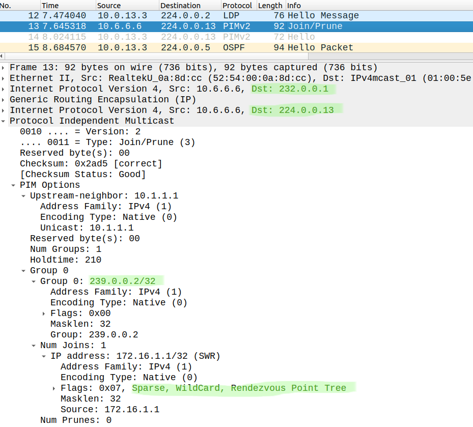
The PIM Join is still encapsulated using the mdt default SSM group address:
But if R8 sends data packets:
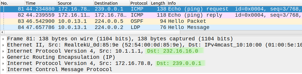
These packets are encapsulated using the first mdt data group (232.16.16.0), but still no MPLS encapsulation. Defining the mdt data groups is not mandatory, this is only optional. So Profile 0 is one of the most straightforward solutions, it is usually applied when the core routers don't support mLDP, if they do we can choose from many other profiles.