Multicast over MPLS: mVPN Profile 1 and Profile 13
After going through how we can configure Profile 0, this time we're going to take a look at two other profiles which both require mLDP. So this is our first requirement: all routers in the core must support mLDP. Regular IOSv routers don't support it, so I replaced everything with CSR1000v routers which do support it, but with some issues (more on this later). If the core router displays similar syslog messages to this one:
%LDP-3-UNKNOWN_MPLS_APP: ldp label mapping message from 10.6.6.6:0; list type 2; afam 65540;
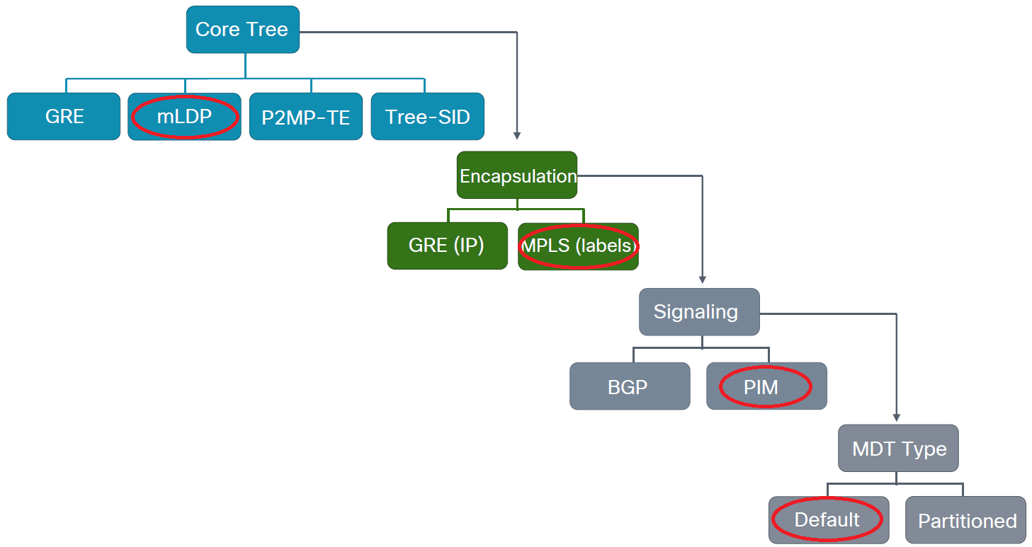
that means bad luck, your core router doesn't support mLDP (or you have to enable it on IOS-XR). So I picked these two profiles because they are very similar, they both require mLDP, and neither of them requires to run PIM in the core. So we're going to build a "PIM-free" core. The difference is the control plane and how we do the signaling: while Profile 1 uses PIM, Profile 13 uses BGP with the mVPN AFI. So first let's build the following topology with Profile 1 first. As you can see we I've replaced everything with CSRs and removed R5 (I'll explain later why).
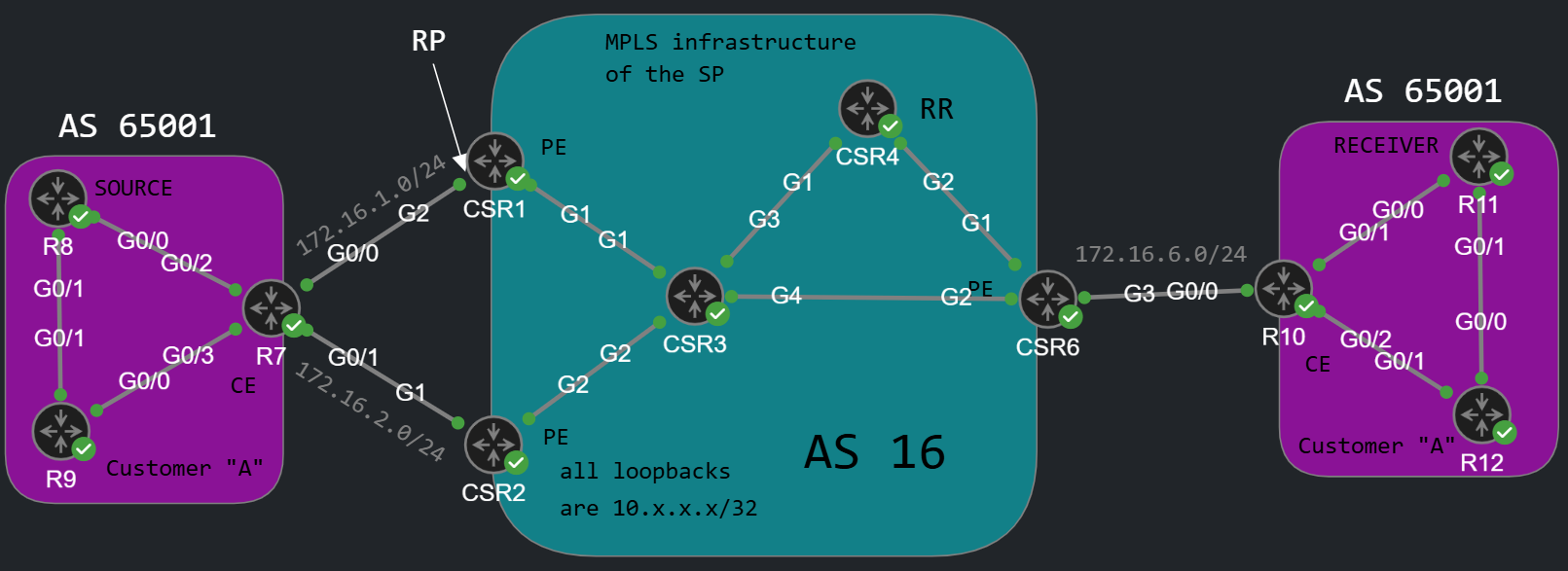
mVPN Profile 1
If we want to convert the Profile 0 configuration, which we've had in the previous lab to Profile 1, the first thing we need to do is that we need to remove the BGP MDT AFI from the PEs and from the Route Reflector. Secondly we can remove PIM from the core: the P routers in the middle don't need to run PIM. The PE routers still run PIM of course on the customer facing VRF interfaces, but not on the interfaces in the global routing table, only on the interfaces in the customer VRFs. In Profile 1 we don't use GRE anymore to tunnel the traffic, the multicast traffic will be MPLS encapsulated.
Just like with Profile 0, we modify the vrf definition as the following on the PE routers, which the customer connects to:
CSR1#show run | sec vrf defvrf definition A rd 16:1 vpn id 16:1 ! address-family ipv4 mdt default mpls mldp 10.3.3.3 route-target export 16:1 route-target import 16:1 exit-address-family
We assign a vpn id to the VRF which has to match on all of the PEs. Besides this we have to designate a router within the core as the mLDP root. In my example I chose CSR3 (10.3.3.3). So we use mLDP to provide the labels within the core for the multicast traffic, here is what the FEC (Forwarding Equivalence Class) binding looks like when CSR6 sends his mLDP Label Mapping message to CSR3:
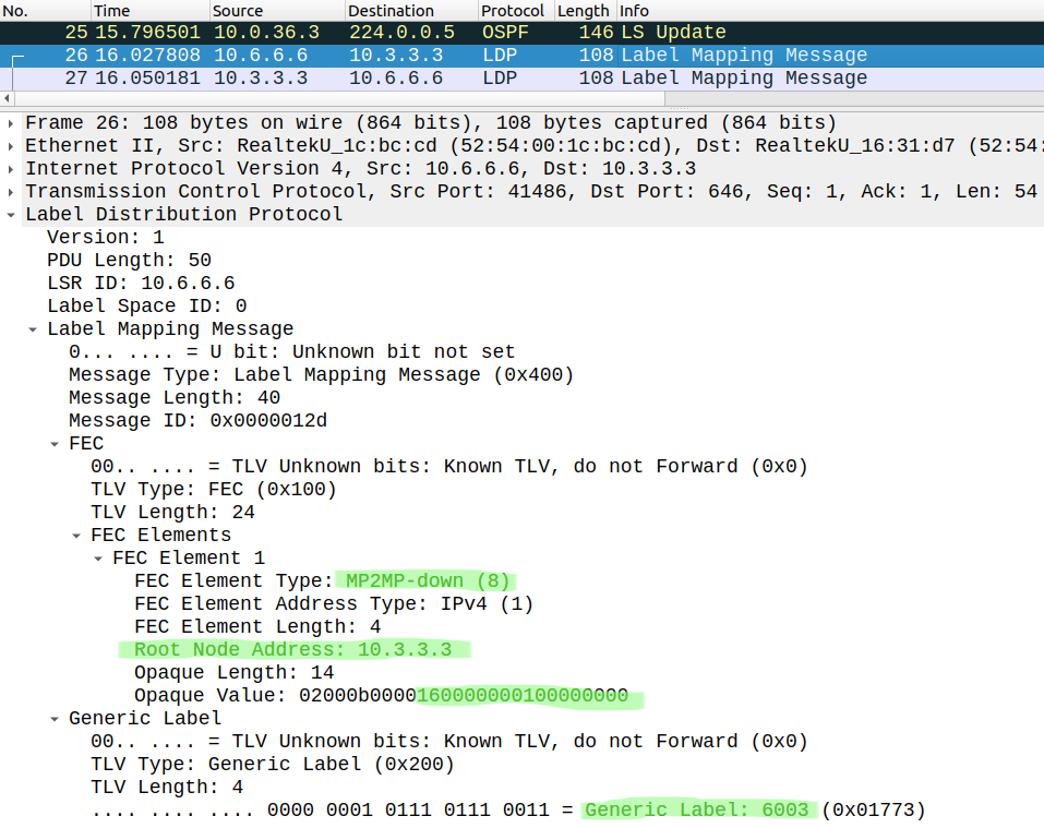
The FEC Element Type is MP2MP downstream, because CSR6 advertises the label that CSR3 should use when he sends the data plane traffic to CSR6. When CSR3 sends his FEC to CSR6 that will be actually upstream, because he advertises a label that CSR6 should use when he sends the multicast traffic up the tree towards the root. The FEC has the IP address of the root (10.3.3.3) as well as the VPN ID as the Opaque Value. Besides that CSR6 also advertises his MPLS label (6003) for multicast traffic.
So after defining the vpn id and the mLDP root with the mdt default mpls mldp command on all PE routers, they should become PIM adjacent via they Lspvif0 virtual interface, which will be created automatically.
CSR1#show ip pim vrf A neighbor PIM Neighbor TableMode: B - Bidir Capable, DR - Designated Router, N - Default DR Priority, P - Proxy Capable, S - State Refresh Capable, G - GenID Capable, L - DR Load-balancing CapableNeighbor Interface Uptime/Expires Ver DRAddress Prio/Mode172.16.1.7 GigabitEthernet2 01:27:59/00:01:20 v2 1 / DR S P G10.2.2.2 Lspvif0 00:10:20/00:01:44 v2 1 / S P G10.6.6.6 Lspvif0 00:12:48/00:01:43 v2 1 / DR S P G
As you can see the configuration of Profile 1 is not complicated at all, we just need to modify the vrf definition with two additional commands on the PEs, and they'll become PIM adjacent. We don't use BGP here, the signaling of the multicast group memberships is done with PIM. Remember we still don't use PIM in the core! The routers are PIM adjacent though their virtual Lspvif0interface in the customer VRF, not in the global table. Let's take a look how the signaling actually works: R11 joins the group 239.0.0.2 and sends an IGMP Membership Report to R10, who creates a (*,G) entry in his mroute table and sends a PIM Join towards the RP.
R11(config-if)# ip igmp join 239.0.0.2
This is how the PIM Join looks like in the core when CSR6 sends it to CSR3:
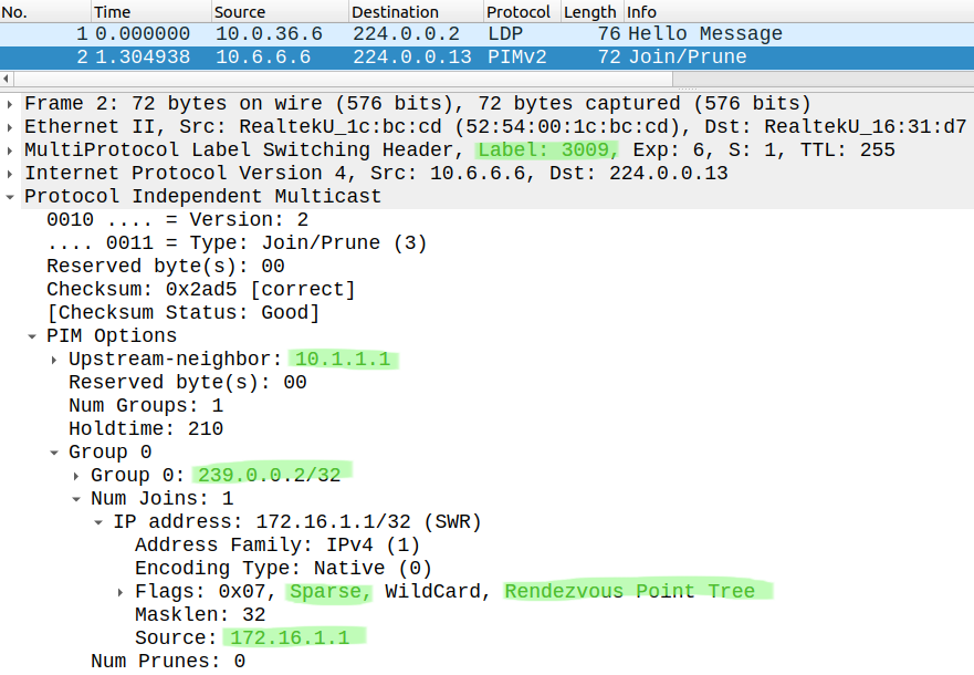
This time the PIM Join is actually MPLS encapsulated with the label CSR3 sent to CSR6 (3009). The RP is still the VRF interface of CSR1, so the Upstream Neighbor is CSR1, and since R11 didn't specify the source we build the shared tree (Rendezvous Point Tree) towards the RP. Eventually the PIM (*,G) Join reaches the RP, and CSR1 creates (*,G) entry in his own mroute table:
CSR1#show ip mroute vrf A | sec 239.0.0.2(*, 239.0.0.2), 00:11:22/00:02:56, RP 172.16.1.1, flags: S Incoming interface: Null, RPF nbr 0.0.0.0 Outgoing interface list: Lspvif0, Forward/Sparse, 00:02:08/00:02:56
So we can verify that the control plane works perfectly. Now let's take a look at the data plane... I can't actually show the data plane, I couldn't make it work on this IOS-XE platform. I think mLDP is somehow broken on the CSR1000v routers. That's why I removed R4 from the topology, that I mentioned at the beginning of the post. If the PEs were not directly connected to the mLDP root (CSR3 in this example) they just couldn't become PIM neighbors for some reason, or one router saw the others as neighbor, but the other two didn't, or the PIM adjacencies were just flapping. This is not a requirement of course, the root can be anywhere within the core. I might have done something wrong, but I don't think so, I did everything according to the configuration guides. I just think mLDP is just somehow "buggy" on this CSR virtual platform. We'll investigate this mLDP issue a little bit more later, but now let's take a look at Profile 13.
mVPN Profile 13
Profile 13 is very similar to the previous solution except that now we use BGP for both signaling and autodiscovery. Now the PE routers won't become PIM adjacent with each other through the tunnel, but we signal the multicast group memberships with BGP.

First we build the BGP neighborships with the mVPN AFI: we activate the neighbors under the AFI:
R1(config-router)#address-family ipv4 mvpn R1(config-router-af)#neighbor 10.4.4.4 activate R2(config-router)#address-family ipv4 mvpn R2(config-router-af)#neighbor 10.4.4.4 activate R6(config-router)#address-family ipv4 mvpn R6(config-router-af)#neighbor 10.4.4.4 activate R4(config-router)#address-family ipv4 mvpn R4(config-router-af)#neighbor 10.1.1.1 activate R4(config-router-af)#neighbor 10.1.1.1 route-reflector-client R4(config-router-af)#neighbor 10.2.2.2 activate R4(config-router-af)#neighbor 10.2.2.2 route-reflector-client R4(config-router-af)#neighbor 10.6.6.6 activate R4(config-router-af)#neighbor 10.6.6.6 route-reflector-client
Just by doing this the PE routers won't send any NLRIs to each other:
R4#show bgp ipv4 mvpn all summary BGP router identifier 10.4.4.4, local AS number 16BGP table version is 1, main routing table version 1Neighbor V AS MsgRcvd MsgSent TblVer InQ OutQ Up/Down State/PfxRcd10.1.1.1 4 16 11 34 1 0 0 00:02:41 010.2.2.2 4 16 10 25 1 0 0 00:02:25 010.6.6.6 4 16 10 17 1 0 0 00:02:10 0
We also have to modify the vrf definition, and add the following statements:
CSR1(config-vrf-af)#mdt auto-discovery mldp CSR1(config-vrf-af)#mdt overlay use-bgp
We still need an mLDP root in the core, so we won't remove that, the VRF definition looks like the following, this is what we should have on each PE router:
CSR1#show run | sec vrf defvrf definition A rd 16:1 vpn id 16:1 ! address-family ipv4 mdt auto-discovery mldp mdt default mpls mldp 10.3.3.3 mdt overlay use-bgp route-target export 16:1 route-target import 16:1 exit-address-family
This is all we need. Now let's take a look at how the signaling works with BGP. We test it with R11 the same way as with Profile 1, R11 joins the 239.0.0.2 multicast group:
R11(config-if)# ip igmp join-group 239.0.0.2
This time R6 sends a BGP mVPN Update to the Route Reflector, and the Route Reflector forwards it to the other two PEs. This is the BGP Update which CSR1 receives from the Route Reflector:
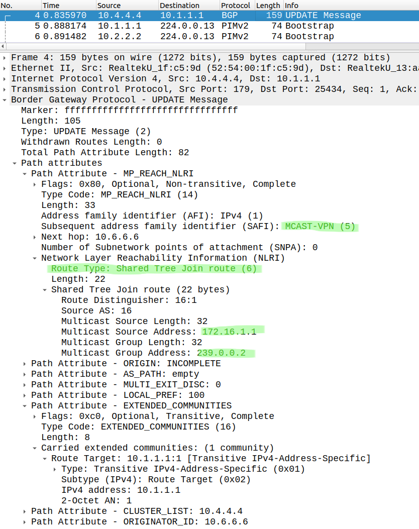
Now the BGP NLRI contains the multicast group we send the PIM Join for. It show that the router wants to join the (*,G) shared tree, and that PIM Join was sent towards the RP which is CSR1 (172.16.1.1). This is how BGP table of CSR1 looks like:
CSR1#show bgp ipv4 mvpn all | begin Netwo Network Next Hop Metric LocPrf Weight PathRoute Distinguisher: 16:1 (default for vrf A) *> [1][16:1][10.1.1.1]/12 0.0.0.0 32768 ? *>i [1][16:1][10.2.2.2]/12 10.2.2.2 0 100 0 ? *>i [1][16:1][10.6.6.6]/12 10.6.6.6 0 100 0 ?Route Distinguisher: 16:2 *>i [1][16:2][10.2.2.2]/12 10.2.2.2 0 100 0 ?Route Distinguisher: 16:6 *>i [1][16:6][10.6.6.6]/12 10.6.6.6 0 100 0 ?Route Distinguisher: 16:1 (default for vrf A) *>i [6][16:1][16][172.16.1.1/32][239.0.0.1/32]/22 10.6.6.6 0 100 0 ? *>i [6][16:1][16][172.16.1.1/32][239.0.0.2/32]/22 10.6.6.6 0 100 0 ?
We can also see that CSR6 previously sent a join for the 239.0.0.1 group as well. These BGP Updates also create a (*,G) Join entries in the mroute table of CSR1, so we can verify that the control plane works. Unfortunately I wasn't so lucky with the data plane, I had the same issues as in Profile 1. But interestingly everything related to the control plane went through the MPLS core, here is a PIM Bootstrap message advertising the RP:
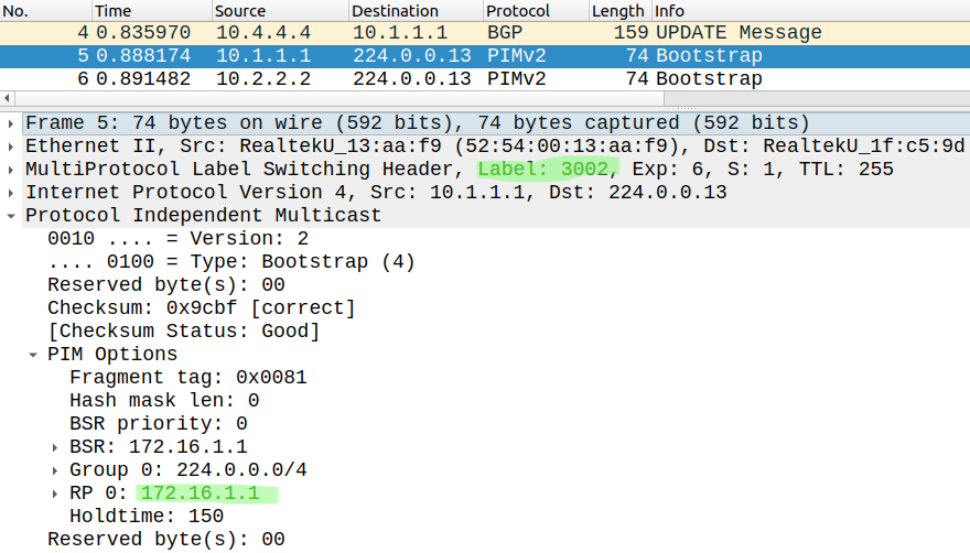
CSR1 sent this PIM Bootstrap to CSR3 encapsulating with the label 3002, which CSR3 has generated previously and sent to CSR1 using mLDP. Here is the LFIB table of CSR3:
CSR3#show mpls forwarding-table | sec Local|mdtLocal Outgoing Prefix Bytes Label Outgoing Next Hop 3002 2013 [mdt 16:1 0] 25936 Gi2 10.0.23.2 6016 [mdt 16:1 0] 4556 Gi4 10.0.36.6 3003 1013 [mdt 16:1 0] 13720 Gi1 10.0.13.1 6016 [mdt 16:1 0] 2668 Gi4 10.0.36.6 3009 1013 [mdt 16:1 0] 576 Gi1 10.0.13.1 2013 [mdt 16:1 0] 576 Gi2 10.0.23.2
We can verify that CSR3 has created the label 3002, when CSR3 receives a packet with label 3002, he forwards it to both CSR2 (using label 2013) and CSR6 (label 6016). And here is the LFIB of CSR1:
CSR1#show mpls forwarding-table | sec Local|mdtLocal Outgoing Prefix Bytes Label Outgoing Next Hop 1013 [T] No Label [mdt 16:1 0][V] 0 aggregate/A
CSR1 has generated the label 1013 which we can see as the outgoing label for the Gi1 interface in the LFIB of CSR3. As I mentioned, for some reason CSR1 couldn't forward data plane multicast traffic towards the root (CSR3). I suppose the multicast traffic should be MPLS encapsulated with the label 3002 when CSR1 forwards it to CSR3, but for some reason CSR1 couldn't send anything on the data plane. Again, I think this issue is related to the CSR1000v virtual image. I might try this on IOS-XR platform in the future just to make sure I didn't make any mistakes with the configuration.