Spanning-Tree Deep Dive: Convergence, Topology changes, BPDU formats, Uplinkfast, Backbonefast
In this post we're going to examine how Spanning-Tree converges when we enable/disable interfaces, or add new switches to an existing topology. We're going to examine the different BPDU types the switches send to each other during topology change for both the classic Spanning-Tree protocol (802.1d) and for the Rapid STP (802.1w) as well. This is rather an advanced topic, but definitely needed if you're learning for the CCNP ENCOR for example. So I won't start from zero and show how the Root Bridge is elected, and how to calculate the Root Path Cost for example. The topology we're going to work with is relatively simple:
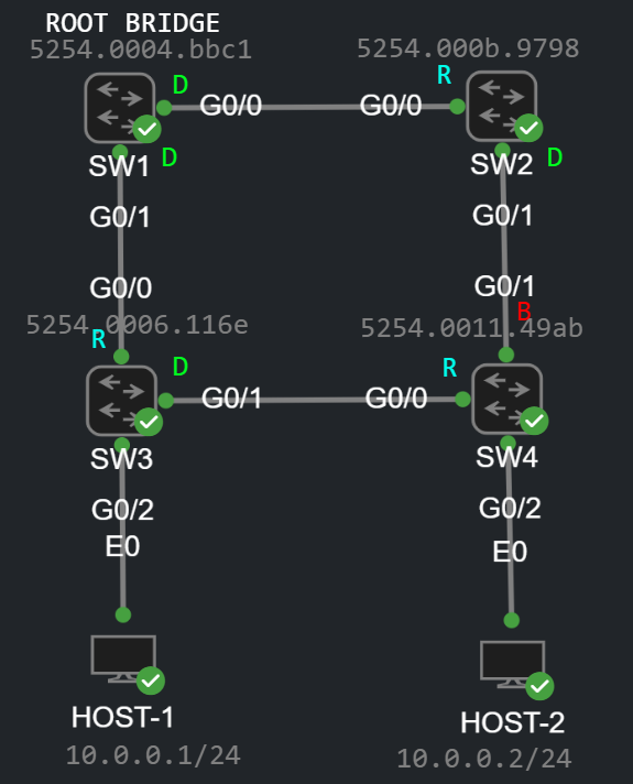
For the sake of simplicity I only have a single VLAN, the default VLAN 1, I set the priority of SW1 to 0, so SW1 is the Root Bridge in this topology. You can also see the port states on the topology diagram in the stable state of the topology (D=Designated, R=Root, B=Blocked [Alternate]). This is how the output of the show spanning-tree on SW4 for example:
SW4#show spanning-treeVLAN0001 Spanning tree enabled protocol ieee Root ID Priority 1 Address 5254.0004.bbc1 Cost 8 Port 1 (GigabitEthernet0/0) Hello Time 2 sec Max Age 20 sec Forward Delay 15 sec Bridge ID Priority 32769 (priority 32768 sys-id-ext 1) Address 5254.0011.49ab Hello Time 2 sec Max Age 20 sec Forward Delay 15 sec Aging Time 300 secInterface Role Sts Cost Prio.Nbr Type------------------- ---- --- --------- -------- --------------------------------Gi0/0 Root FWD 4 128.1 P2p Gi0/1 Altn BLK 4 128.2 P2p Gi0/2 Desg FWD 4 128.3 P2p Edge
I enabled Portfast on G0/2 (I did the same on SW3), so it shows P2p Edge in the Type column, we'll see later that the switches don't generate TCN BPDUs when a Portfast enabled interface changes its state (goes up or down). As you can see we're running ieee aka. classic Spanning-Tree (so Rapid STP is not enabled at this point on any switches), Cisco has his own implementation of classic STP, called PVST which allows to define a different STP instance for each VLAN. The Priority (1) above in the output is basically the System ID Extension which is the Bridge Priority (which I set to 0 on SW1) + the VLAN ID (which is 1 in this case). So the Priority here is a bit deceptive, it's not the actual priority you would set on the Root Bridge, but it's the System ID Extension. In the followings we're going to take a look at how Spanning-Tree converges when we enable/disable interfaces or add new switches to an existing topology.
Scenario No. 1 - Disconnect the link between SW3 and SW4
First of all I'm going to turn on the following debugging on all of the switches, so that we can examine what's happening in the background when we mess up with the topology:
SW4#debug spanning-tree events Spanning Tree event debugging is on
In CML I simply disconnect the link with the "Disconnect" button:
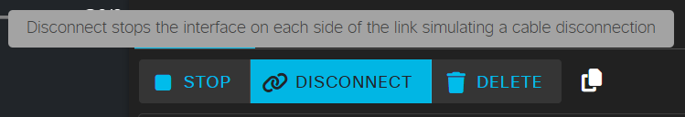
The interfaces on both sides are now in the down/down state, so we're simulating a link failure. This is what happens on SW4:
*Oct 25 09:42:13.647: %LINEPROTO-5-UPDOWN: Line protocol on Interface GigabitEthernet0/0, changed state to down*Oct 25 09:42:14.647: %LINK-3-UPDOWN: Interface GigabitEthernet0/0, changed state to down*Oct 25 09:42:30.385: STP: VLAN0001 new root port Gi0/1, cost 8*Oct 25 09:42:30.385: STP: VLAN0001 Gi0/1 -> listening*Oct 25 09:42:45.385: STP: VLAN0001 Gi0/1 -> learning*Oct 25 09:43:00.385: STP[1]: Generating TC trap for port GigabitEthernet0/1*Oct 25 09:43:00.386: STP: VLAN0001 sent Topology Change Notice on Gi0/1*Oct 25 09:43:00.386: STP: VLAN0001 Gi0/1 -> forwarding
SW4 expects to receive BPDUs from the Root Bridge on interface G0/0 since this is his Root port. SW4 waits until the Max Age timer (~20 seconds) expires, declares his upstream neighbor (SW3) dead, and then he chooses a new Root port, which will be G0/1 because this interface has the lowest Root cost. Now he has to go though the Listening and Learning states which takes two times 15 seconds. Once the port turns into the Forwarding state, SW4 generates a Topology Change Notification (TCN) BPDU and sends out on his new Root port G0/1. Let's take a look at this BPDU:
Note: On a real physical equipment SW3 would also generates a TCN because his interface G0/1 goes down, and STP would stop running on that interface. Unfortunately the emulation of IOS switches in CML and GNS3 has some issues: even if the port goes down operationally, STP still operational, and the switch shows that G0/1 is still designated and forwarding. If you shut down the interface administratively, then STP will actually stop running on the interface and the switch will actually generate a TCN (I'll show this later), but the emulated environment unfortunately can't handle a link failure and couldn't detect if a port goes down. This is a limitation of GNS3 and CML (I suppose the same thing is true for EVE-NG).
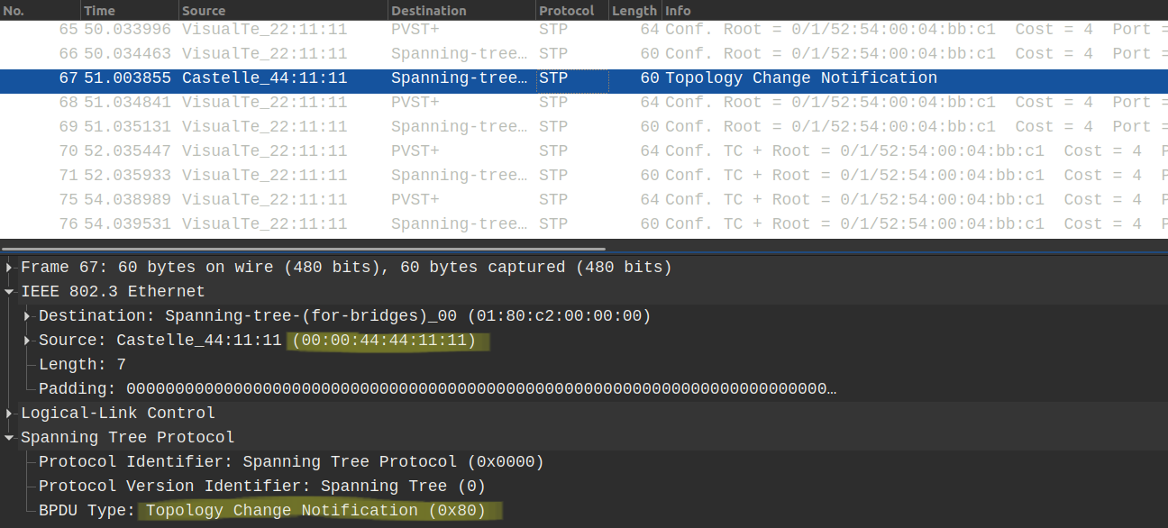
In the stable state of the topology only the Root Bridge (SW1 in this case) is allowed to send BPDUs. The downstream switches receive this BPDU on their Root Port, they increase the Root Path Cost with their interface cost which they received the BPDU on, and then forward it out of their designated ports towards the other downstream switches. These BPDUs are called Configuration BPDUs. However when something happens in the topology, other switches are also allowed to send TCN BPDUs out of their Root Port towards their upstream neighbor. So when do the switches actually send these TCN BPDUs? With the classic 802.1d Spanning Tree switches send TCNs when any of their ports transitions to the Forwarding state or when a port in a Listening or Forwarding state turns into the Blocking state.
Unlike the Configuration BPDU, the TCN BPDU is actually very simple, doesn't have too much information as you can see above. It only indicates that something has happened in the topology, we don't know whether an interface went down or up, or which switches were actually affected. SW2 receives the TCN, and sends back a Topology Change Acknowledgement (TCA) to SW4:
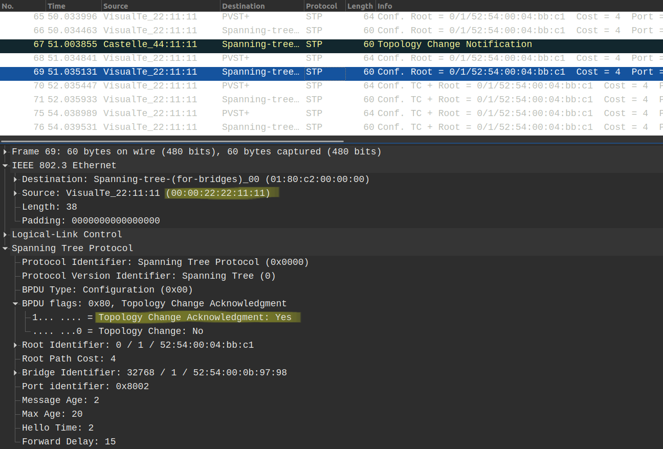
Notice that the TCA is actually a Configuration BPDU with the TCA flag set to 1. SW4 keeps sending their TCNs towards SW2 until he receives the TCA BPDU above. Now what does SW2 do besides sending the Acknowledgement? This is the debug captured on SW2:
*Oct 25 09:42:58.720: STP: VLAN0001 Topology Change rcvd on Gi0/1*Oct 25 09:42:58.720: STP: VLAN0001 sent Topology Change Notice on Gi0/0
SW2 forwards the TCN out of his Root Port G0/0 towards the Root Bridge. So the TCNs are always sent upstream towards the Root Bridge. Once the Root Bridge receives a TCN, it generates a new Configuration BPDU with the Topology Change (TC) field set to 1. The other switches forward these BPDUs, just like any other Configuration BPDUs out of their Designated ports towards their downstream neighbors.
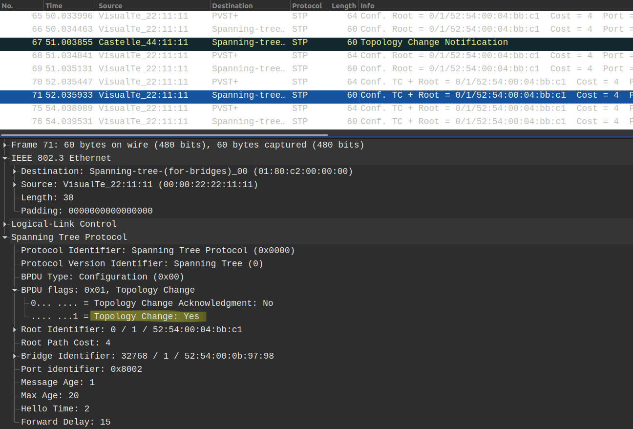
The Root Bridge generates these Configuration BPDUs (with the TC bit set to 1) for 35 seconds by default (Max Age + Forward Delay Time). So at first switches forward the TCN BPDUs upstream towards the Root Bridge, now it's the responsibility of Root Bridge to notify every other downstream switch about the topology change. The Root Bridge does this by setting the TC bit to 1 in his Configuration BPDUs. This way every switch will be notified about the topology change. Switches don't need know what changed, switches who receive the Configuration BPDU only know that something has changed. Whether an interface went down or a new switch was added to the topology that doesn't really matter.
Now what do switches do when they receive these Configuration BPDUs with the TC bit set to 1? They decrease the MAC address aging time drastically, from 300 seconds to just 15 seconds (to be more specific to the value of the Forward Delay Time which is 15 seconds by default). So this is SW3 after receiving the Configuration BPDU with the TC bit:
SW3#show spanning-tree VLAN0001 Spanning tree enabled protocol ieee Root ID Priority 1 Address 5254.0004.bbc1 Cost 4 Port 1 (GigabitEthernet0/0) Hello Time 2 sec Max Age 20 sec Forward Delay 15 sec Bridge ID Priority 32769 (priority 32768 sys-id-ext 1) Address 5254.0006.116e Hello Time 2 sec Max Age 20 sec Forward Delay 15 sec Aging Time 15 secInterface Role Sts Cost Prio.Nbr Type------------------- ---- --- --------- -------- --------------------------------Gi0/0 Root FWD 4 128.1 P2p Gi0/1 Desg FWD 4 128.2 P2p Gi0/2 Desg FWD 4 128.3 P2p Edge
Notice that the Aging Time has been decreased to 15 seconds. Why is this necessary? What would happen if the switches didn't reduce their MAC address aging time? Just think about it! What if SW3 wanted to forward frames to HOST-2? SW3 checks his MAC address table and determines that HOST-2 is reachable via G0/1, so he keeps forwarding the frames out of interface G0/1, however after disconnecting the link HOST-2 is already unreachable via that link. So the two hosts will not be able to communicate with each other for at least 300 seconds, and there would be a traffic black hole. By aging out the learned MAC addresses in 15 seconds ensures that the MAC address will be flushed much more faster from the CAM table. Switches then flood the the unknown unicast frames again out of all of their ports before they learn and populate the CAM table again.
Scenario No. 2 - Reconnect the link between SW3 and SW4
Before I reconnect the link between the two switches, let's take a look at the port states of SW4:
SW4#show spanning-tree VLAN0001 Spanning tree enabled protocol ieee Root ID Priority 1 Address 5254.0004.bbc1 Cost 8 Port 2 (GigabitEthernet0/1) Hello Time 2 sec Max Age 20 sec Forward Delay 15 sec Bridge ID Priority 32769 (priority 32768 sys-id-ext 1) Address 5254.0011.49ab Hello Time 2 sec Max Age 20 sec Forward Delay 15 sec Aging Time 300 secInterface Role Sts Cost Prio.Nbr Type------------------- ---- --- --------- -------- --------------------------------Gi0/0 Desg FWD 4 128.1 P2p Gi0/1 Root FWD 4 128.2 P2p Gi0/2 Desg FWD 4 128.3 P2p Edge
Note: Same issue that I've already outlined above: even if G0/0 is down/down, SW4 shows that STP is still operational on the interface. On a real, physical equipment G0/0 would simply be omitted from the output above, because STP would stop running on a port in the down state (whether the port is operationally or administratively down, that doesn't matter).
The Root port of SW4 is currently G0/1. When we reconnect the link SW4 is going to change his Root port. The Root Path cost from SW3 is still the same (8), but SW3 has lower Bridge ID. And this is the debug after reconnecting the link:
SW4:*Oct 25 09:58:40.626: STP: VLAN0001 new root port Gi0/0, cost 8*Oct 25 09:58:40.626: STP: VLAN0001 sent Topology Change Notice on Gi0/0*Oct 25 09:58:40.626: STP[1]: Generating TC trap for port GigabitEthernet0/1*Oct 25 09:58:40.626: STP: VLAN0001 Gi0/1 -> blocking
Notice that G0/0 is already forwarding (it was designated before receiving the superior BPDU), so G0/0 doesn't have to go through the Listening and Learning states (2x15 seconds), SW4 instantly changes his Root port from G0/1 to G0/0, and G0/1 will be blocking. [ Remember on a real physical equipment, SW4 would have to go through the Listening and Learning states, here G0/0 is only designated because CML doesn't handle STP on an interface in the down/down state properly. ] SW4 generates a TCN for G0/1 since this port moves into the blocking from the forwarding state.
Scenario No. 3 - Shutting down the port G0/1 on SW3 administratively
As I foreshadowed above, unlike the operational down state, administratively shutting down the interface is actually works properly in CML, so STP will actually stop running on the interface, and the switch will generate a TCN, let's take a look:
SW3(config)#int g0/1SW3(config-if)#shut
After shutting down the port, STP stops running on G0/1, and SW3 generates a TCN instantly and sends it out on G0/0 toward the Root Bridge:
*Oct 25 10:31:19.872: STP: VLAN0001 sent Topology Change Notice on Gi0/0*Oct 25 10:31:19.872: STP[1]: Generating TC trap for port GigabitEthernet0/1*Oct 25 10:31:21.847: %LINK-5-CHANGED: Interface GigabitEthernet0/1, changed state to administratively down*Oct 25 10:31:22.847: %LINEPROTO-5-UPDOWN: Line protocol on Interface GigabitEthernet0/1, changed state to down
What happens on SW4? On a physical equipment G0/0 would go down, in CML the line protocol still shows up, so SW4 waits for the 20 seconds until the Max Age timer expires, and then declares his neighbor SW3 dead. Now SW4 chooses a new Root port: SW4 chooses G0/1, and because the port is currently has the Alternate role, it has to transition through the Listening and Learning states (2x15 seconds):
*Oct 25 10:31:40.472: STP: VLAN0001 new root port Gi0/1, cost 8*Oct 25 10:31:40.472: STP: VLAN0001 Gi0/1 -> listening*Oct 25 10:31:55.472: STP: VLAN0001 Gi0/1 -> learning*Oct 25 10:32:10.472: STP[1]: Generating TC trap for port GigabitEthernet0/1*Oct 25 10:32:10.473: STP: VLAN0001 sent Topology Change Notice on Gi0/1*Oct 25 10:32:10.473: STP: VLAN0001 Gi0/1 -> forwarding
Once the port turns into forwarding, SW4 sends a TCN out of his new Root port to SW2. So in this scenario SW1 receives two TCNs:
*Oct 25 10:31:21.924: STP: VLAN0001 Topology Change rcvd on Gi0/1*Oct 25 10:32:10.115: STP: VLAN0001 Topology Change rcvd on Gi0/0
Notice that the TCNs are roughly 50 seconds apart from each other in time, this is because SW4 waited for the Max Age timer (20 sec) to expire + it went through the Listening (15 sec) and Learning (15 sec) states.
---
---
Uplinkfast
as
as
as
as
asd