Automating VRF-aware IPsec VPN with IKEv2 using Netmiko and Jinja2 templates
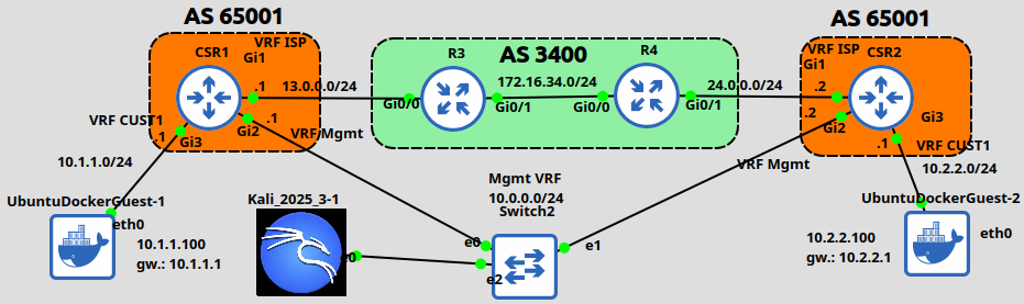
In the previous IPsec posts we established the tunnel using IKEv1 and used the crypto isakmp ... command. Now in this post we'll take a look at how we configure IPsec using the new way, IKEv2. The configuration of IKEv2 is quite different, doesn't have many similarities with IKEv1, and they're incompatible with each other. We'll also take a look at how we can configure IPsec tunnels when our WAN and LAN interfaces are in different VRF. On top of that we're going to automate the whole thing, and push the configuration to the routers using a Python script, and we'll create our configuration of the routers using Jinja2 templates. But first let's take a look at the lab topology:
I uploaded my Python script, the Jinja2 template, the YAML file, and the full IPsec configuration of the CSR routers to this GitHub repo. Feel free to download.
We're going to establish our tunnel between the CSR1 and CSR2 routers. I have already preconfigured the VRFs, the IP addresses and the BGP routing in our lab. Because both CSRs are in the same AS, I used the allowas-in feature on both sides so that the routers can accept prefixes from their own AS. The WAN interface (Gi1) on both routers are in the "ISP" VRF, and the customer LAN interface (Gi3) on both routers are in the "CUST1" VRF. And we're managing the routers from the Mgmt VRF (10.0.0.0/24 subnet) from the Kali host. So both routers have three interfaces configured with three different VRFs, and the GRT (global routing table) is not used at all. So there is already IP reachability between the WAN interface of CSR1 (13.0.0.1) and CSR2 (24.0.0.2). Our customer subnets (10.1.1.0/24 on CSR1 and 10.2.2.0/24 on CSR2) are not able to reach each other at this point of course. Our goal is to establish a secure communication between them by establishing an IPsec tunnel between the CSR routers.
1 - Automating the IKEv2 config
Let's actually start with the ipsec_ikev2.j2 template file I created:
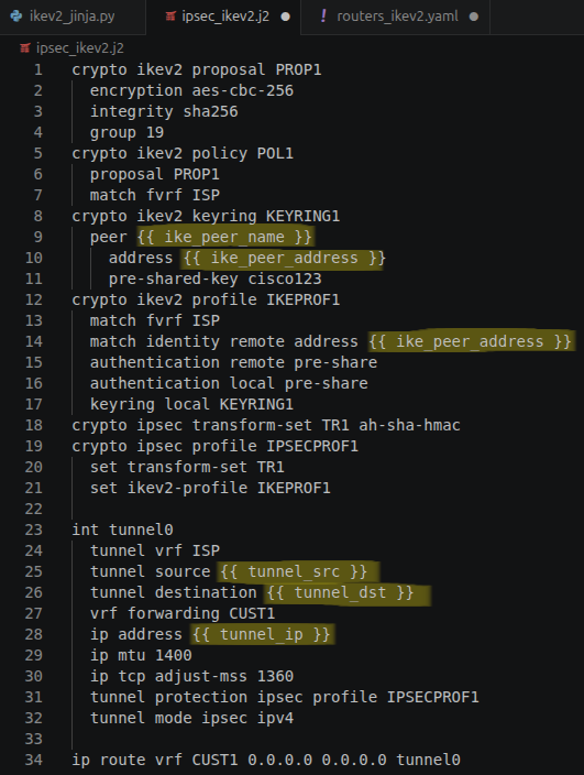
Because the configuration of both sides will be very similar, I though this is a great way to demonstrate how the Jinja2 templates can be used for network automation. Later I'll explain in details, but this configuration above is what we'll push to our routers to establish the tunnel. Notice the parameters in yellow between the curly brackets, these will be different for each router (like the tunnel IP address, IP address of the peer etc.). Next let's take a look our routers_ikev2.yaml file:
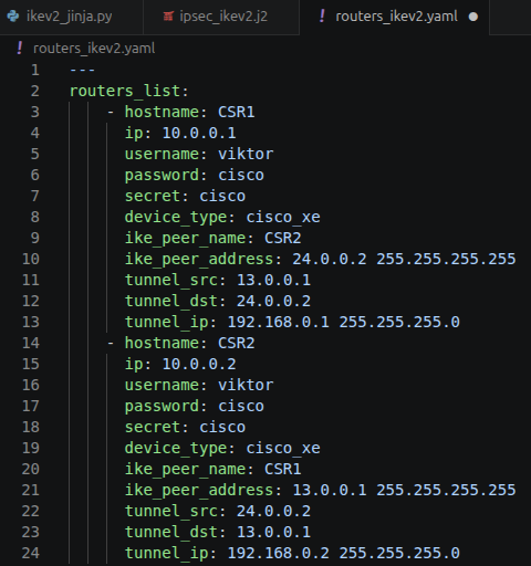
This is where we list the parameters for the template file (like tunnel_ip, ike_peer_address etc.) and also the parameters for the Netmiko SSH session which we've already seen in the previous Netmiko post.
These two are both needed to run the ikev2_jinja.py script:
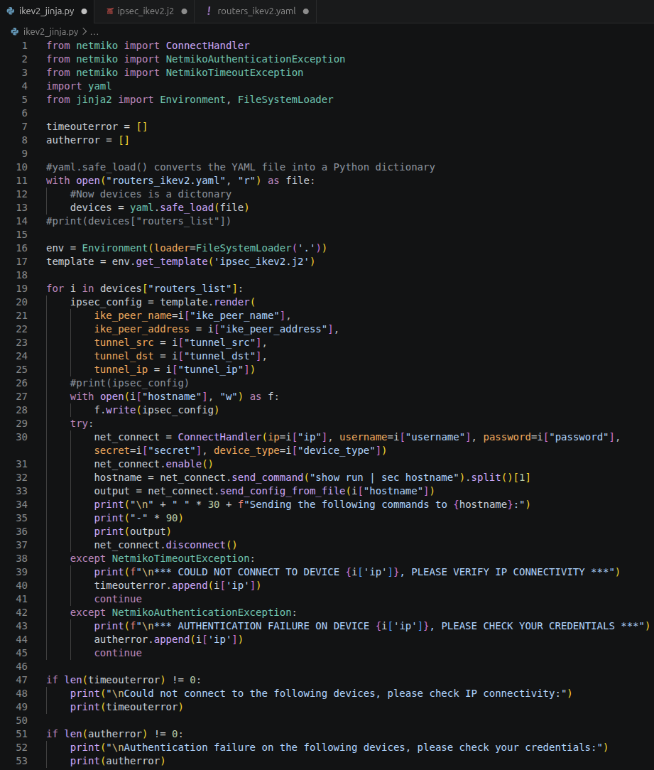
First with the yaml.safe_load() method we convert our YAML file into a Python dictionary, then with the env.get_template() we load our ipsec_ikev2.j2 template file. Our routers_list within the YAML file contains two elements (CSR1 and CSR2), we're looping through these elements with the for loop, then with the template.render() we basically replace our parameters within the curly brackets {{ ... }} in the ipsec_ikev2.j2 template file with the parameters from the YAML file (which is now a Python dictionary). After replacing each parameter we have an IPsec configuration for each device ready to be pushed to each device. The script writes the configuration for of each device into a separate file into the current working directory. This is the config of CSR2 for example:
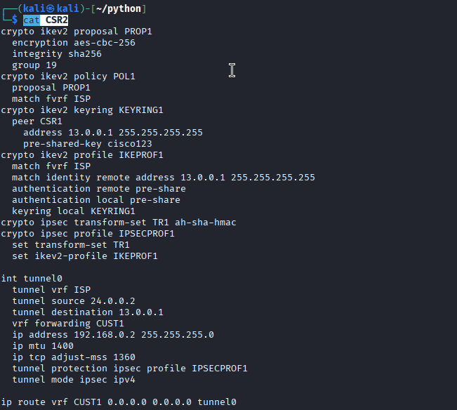
Notice that the values between the {{ ... }} curly brackets have now been replaced with the values from the YAML file. We use these files to send the commands to the routers using the send_config_from_file() Netmiko method that I've already introduced in the previous Netmiko post. Remember that now in this lab we just have two routers, but in a DMVPN environment for example we can have hundreds of spoke routers. Writing an individual IPsec config for example for each router does not scale very well. Creating a a single Jinja2 template file and an entry in the YAML file for device-specific parameters is a much more scalable method. And finally this is how it looks like when we run the script:
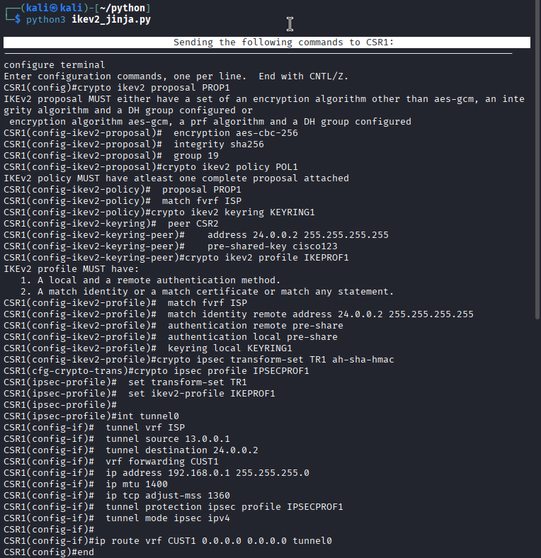
2 - The IKEv2 IPsec configuration
As it can be seen above IKEv2 is quite different from IKEv1, but there are a few similarities. First we create a Proposal: this is where we define our crypto parameters to protect subsequent IKE messages, like we did under the crypto isakmp policy command with IKEv1, except the authentication and lifetime. These are not negotiated with IKEv2 in the first message request/response exchange (as we'll see later). Creating the Proposal is optional: there is a default Proposal already defined on the CSR router. The Proposal must be referenced under the IKEv2 Policy.
In addition Policies optionally can have one or more match statements to specify the context. By default the Policy matches anything, here I associated it with the fVRF which is named "ISP" in our case. Next we create the Keyring which is mandatory.
An interesting feature of IKEv2 (which is different from IKEv1) is that we can use asymmetric authentication: local device can use a different authentication method than the remote device (PSK vs. certificates for example). In addition IKEv2 also supports EAP for authentication, and we can even store our PSKs on a RADIUS server.
So the Keyring in our case is a local repository for the pre-shared keys that will be used for authentication. Under the Keyring we put each of our peers into blocks, where we can define the WAN-facing public IP address of the peers and the corresponding PSK which we use for authentication. Here we specify symmetric authentication (same key for both CSR1 and CSR2). If we used asymmetric key pairs we would specify that with the pre-shared-key local | remote keywords.
The Keyring must be referenced under the IKEv2 Profile: again this is mandatory. The IKEv2 Profile is used to define the authentication methods and the peers who we can establish the IPsec tunnel with. As the warning message denotes: we need local/remote authentication methods, and a match identity statement for the remote peer. Finally the IKEv2 will be referenced under the IPsec profile, which will be used for the tunnel protection. This is how we tie everything together.
3 - Front-door VRF (fVRF) vs internal VRF (iVRF)
In the previous IPsec posts we had every interface in the default VRF (global routing table) configured. This lab is different in this aspect as well: our customer hosts are in the "CUST1" VRF on both routers, and the WAN interface (Gig1 on both devices) is configured in a different VRF called "ISP" on both devices. In this lab our fVRF will be the "ISP" VRF. This will be in the routing table where our tunnel source and tunnel destination reside. We configure this with the tunnel vrf ISP command under the tunnel interface. Now we must have a valid route in the routing table of the "ISP" VRF to the IP address of the tunnel destination, and also the interface of the tunnel source must be configured in this VRF. So in short the fVRF is used to the send the encapsulated data (ESP/AH packets), i.e. this is our underlay.
You'd probably figured out that the iVRF will be used for the overlay, the non-encapsulated data. The LAN-facing interfaces (where our hosts reside) are configured in the iVRF, which is called "CUST1" in our case. In addition, the tunnel interface is also configured in this VRF with the vrf forwarding CUST1 command. Lastly I created a default route for the "CUST1" VRF in the end of the configuration pointing to the tunnel interface, so that we can forward packets between the two customer LAN subnet.
Notice that I specified the tunnel0 interface for the default route, not the IP address of the tunnel interface of the other side as the next-hop. Since our tunnel0 is an endpoint of a point to point tunnel, this won't cause any problem in this case. Otherwise if the next-hop were an Ethernet interface this wouldn't work of course, we would need to use the IP address in that case.
4 - IKEv2 message exchanges, IPsec tunnel establishment
Not just the configuration, but also the message exchanges are different with IKEv2. Using IKEv1 with Main Mode, we need 9 messages in total to create the IPsec SAs: 6 messages for Main Mode (phase 1), and 3 messages for Quick Mode (phase 2). With IKEv2 we only need four! Let's take a look at the IKEv2 messages:
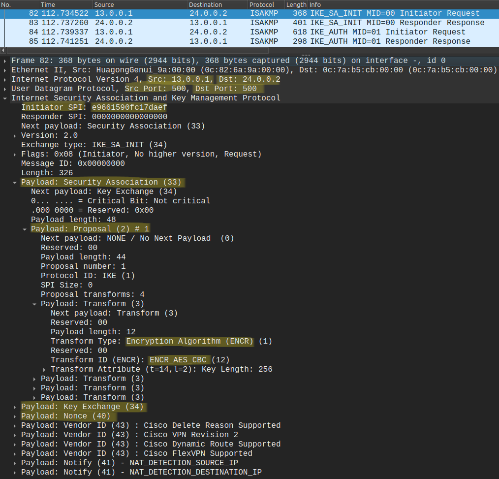
IKEv2 messages are always sent in request/response pairs. With IKEv2 we don't have a concept of Main Mode (MM), Aggressive Mode (AM) or even Quick Mode (QM). Because of that IKEv2 is not backward compatible with IKEv1. The IKE_SA_INIT is our initial handshake, this is where the CSR routers negotiate the crypto algorithms for phase 1 (the parameters we specified in the Proposal). In addition we also do the Diffie-Hellman key exchange with the nonces in the first two messages. So the first IKE_SA_INIT message pair is equivalent to the first four messages in MM (MM1 - MM4).
Because the keys exchanged in the first two messages are computationally "expensive", IKEv2 can actually be vulnerable to DoS attacks, where the attacker sends many IKE_SA_INIT messages from spoofed source IP addresses, and as a response, the router needs to generate cryptographically expensive keys. (But with IKEv2, the routers can also implement anti-DoS capabilities when they detect many half-open IKEv2 connections).
The second request/response message pair is the IKE_AUTH, this is where the identity of the peers will be validated:
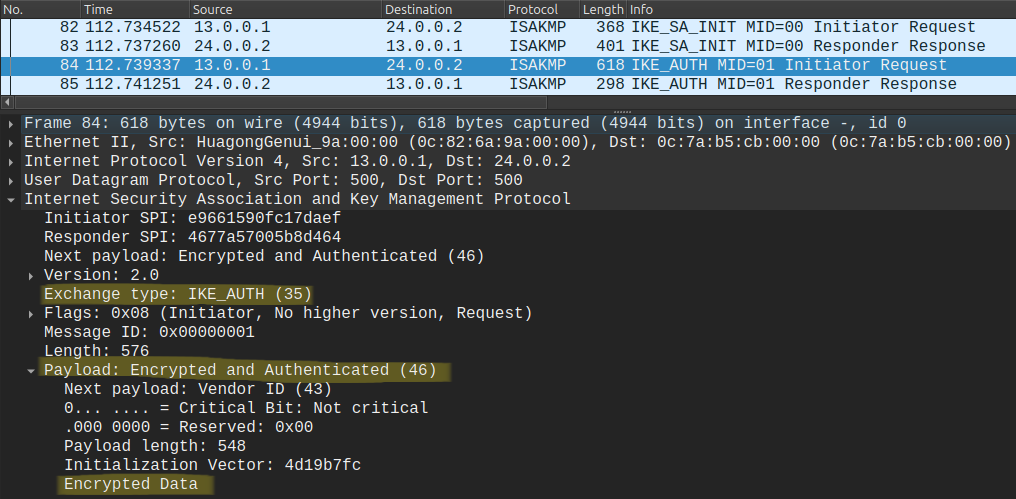
Because the Diffie-Hellman key exchange resulted a common shared secret for both routers, all messages following IKE_SA_INIT are already encrypted using the security algorithms obtained from the initial handshake, as we can see above. Here in this message exchange each router provide authentication data to validate the identity of the remote peer. This message exchange is equivalent to MM5 - MM6, and QM1 - QM2. After a successful IKE_AUTH exchange, and after the fourth message we have a single pair of IPsec SAs (unidirectional!) created.
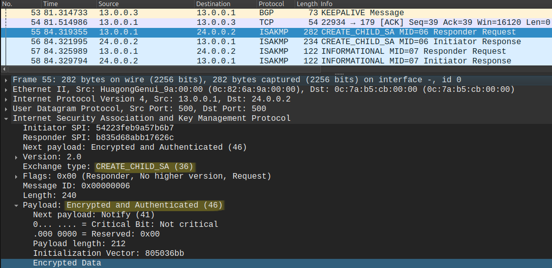
For subsequent IPsec SAs the peers use the CREATE_CHILD_SA messages. This is used when the SA expires (lifetime or the maximum amount of traffic is reached), and the peers have to rekey. The INFORMATIONAL exchange can be used to delete the previous IPsec SAs:
5 - Control and data plane verification
For verification of the IKE SAs we can use the following command:
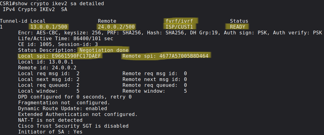
We can verify the local/remote IPs, the fVRF/iVRF, and the Status which should display "READY" in case of a successful negotiation. For the phase 2 (IPsec) verification we use the same command as we'd use with IKEv1:
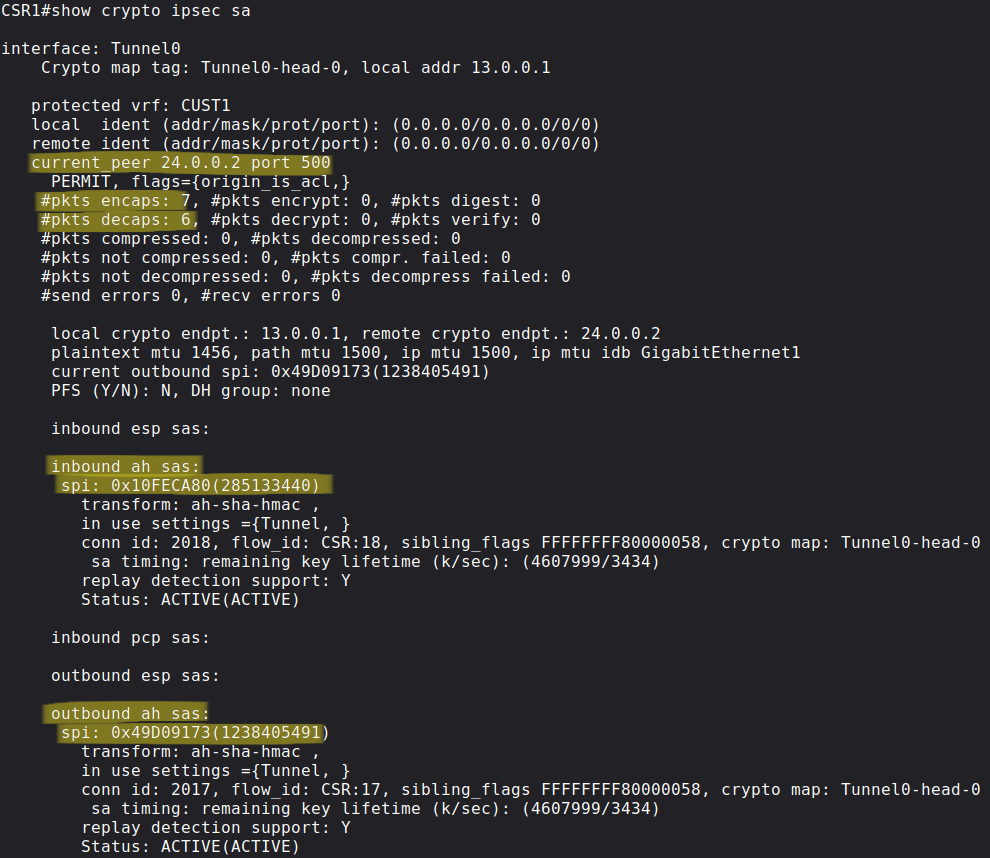
Here the counter of thepkts encaps/decaps or the pkts encrypt/decrypt (depending on the protocol) should increase, this indicates that the data plane is working correctly. We have two unidirectional SAs with unique SPI (Security Parameter Index) values, these are used to identify the SAs on the routers, so that the router will know which crypto algorithms and keys it should use the decrypt the packets. Remember that the SPIs are transferred in clear text in both the ESP and the AH headers. Here is an example of a data plane packet which the Ubuntu host 1 sent to Ubuntu host 2:
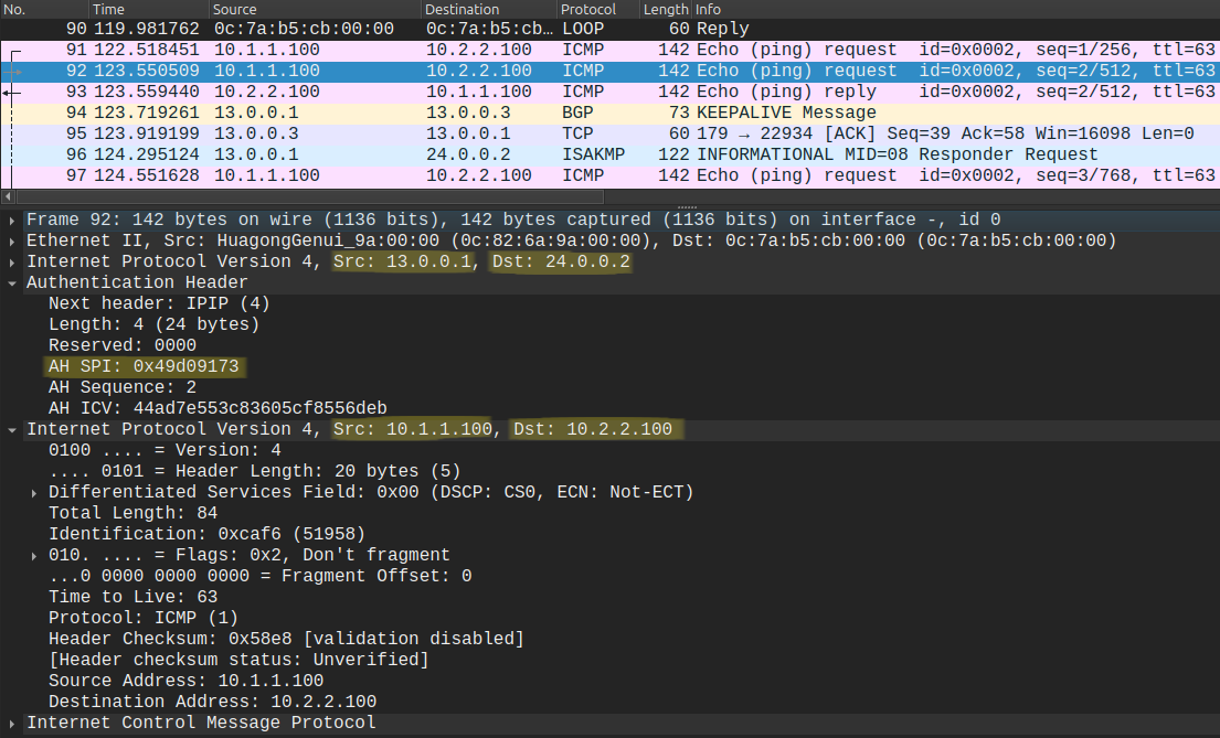
In this example CSR1 sends the encapsulated packet to CSR2, notice the SPI (0x49d09173) which corresponds to the outbound SA on CSR1. Just as in the previous examples I use AH instead of ESP. AH is only used to verify the integrity of the messages on the remote side (the messages can't be modified in transit), but it won't encrypt the messages, so that we can see the inner IP headers in Wireshark.
6 - Static VTI
I did this so that we can explore one more command on the tunnel interface: tunnel mode ipsec ipv4. Notice the pcap above: there is no GRE header! This is because I changed the tunnel mode from the default GRE IP to IPsec IPv4. This is called static VTI (Virtual Tunnel Interface). With this one we can get rid of the GRE header and an encapsulated IP header. For comparison this is how our data plane would look like with the default GRE/IP tunnel mode (without the tunnel mode ipsec ipv4 command):
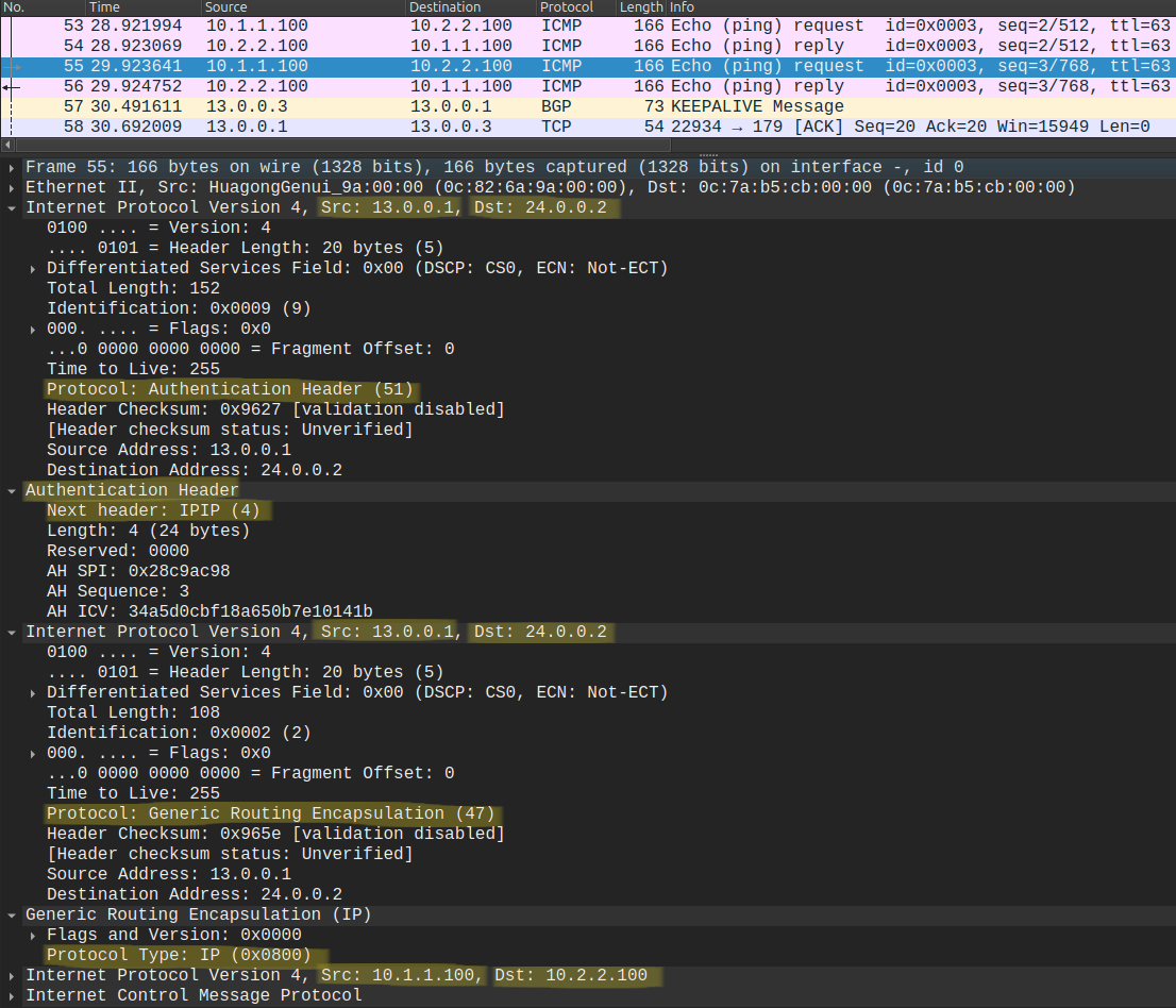
What a mess, we have three IPv4 headers, a GRE header and an AH header. So using the Static VTI we remove the IPv4 header following the AH and the also the GRE header. The VTI carries the IP traffic directly within the IPsec tunnel. The advantage is obviously less overhead, the disadvantage is that we can only encapsulate IP traffic. GRE is much more flexible in this regard, with GRE we can basically encapsulate almost anything. But because we're only sending IP traffic between the hosts, this won't really be a disadvantage.
7 - Changing the transform-set: encrypting everything with ESP
To demonstrate how easy it is to change the IPsec transform-set on all routers using network automation let's say that we want to provide confidentiality between the Ubuntu hosts and encrypt everything. To do this we have to change the transform-set on both routers to ESP. Now we only have two routers but image hundred routers, you won't SSH in to each of them and issue the same CLI command. In our case we only need to modify our Jinja2 template file and change the transform-set:
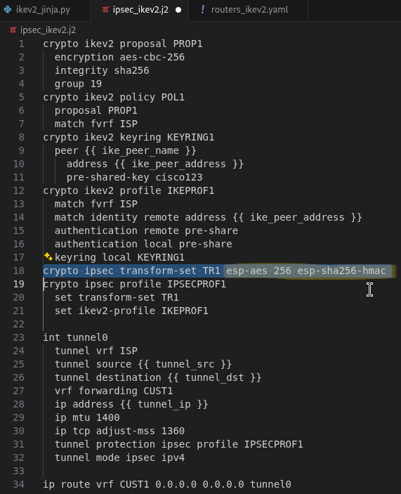
Here I use AES-256 for encryption and and SHA256-HMAC (hashing) to verify message integrity. After modifying the .j2 template we just run the script again, and we're done, now the traffic between the Ubuntu hosts are encrypted:
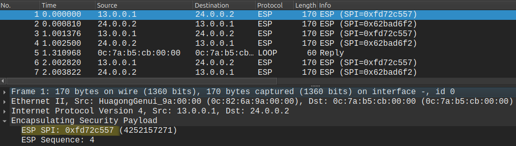
Notice that the SPI values are still in clear text! This is because the routers need this to identify the encryption algorithms and keys (the IPsec SA) to be able to decrypt the packets.