Implementing VXLAN on NX-OS part 2: Anycast RP with MSDP, Phantom RP, BGP EVPN, inter-VXLAN routing with Symmetric IRB
We continue the previous VXLAN lab first by providing redundancy for the RP. I'll show two methods: Anycast RP with MSDP and Phantom RP which works with PIM Bidir. Next I'll show how BGP EVPN works as the control plane between the VTEPs and lastly we'll see how we can route packets between different VLANs using anycast gateway.
Rendezvous Point redundancy techniques
Anycast RP with MSDP
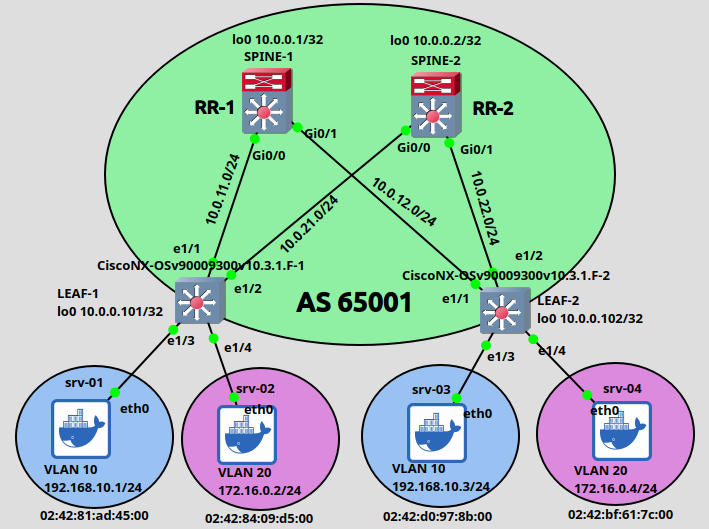
We can easily see that if we have a single RP which goes down, the multicast flooding mechanics breaks and we won't be able to send packets between the VTEPs. With Anycast RP we configure the same loopback address on both Spine switches and this address will be advertised to the Leaf switches as the RP. So I assign exactly the same loopback1 address on both Spines:
interface Loopback1 ip address 10.0.0.201 255.255.255.255 ip pim sparse-mode ip ospf 1 area 0
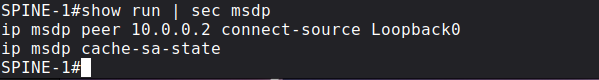
The new address of the RP will be 10.0.0.201 in our case, which we advertise with BSR as I showed in the previous post. It is highly recommended that we assign a unique OSPF Router-ID manually to each Spine switch. If both of the Spine switches use this new Loopback address as their RID (if this new Loopback has the highest loopback address configured on the router) then OSPF breaks. So make sure that the Spines use a unique RID. Next we advertise this new 10.0.0.201 address into OSPF on both Spines and enable PIM SM on the interface. Anycast means nearest routing (this is what we also use with the root DNS servers), PIM Register and Join messages are sent toward the closest RP based on the OSPF topology. In our case Leaf switches now can send multicast packets toward both Spines (because they use ECMP and equal OSPF cost toward each Spine). But we are not done yet, the two redundant RPs also have to talk to each other and synchronize the multicast (S,G) session state between the each other. For this purpose we use MSDP (Multicast Source Discovery Protocol) which basically establishes a TCP session between the two Spines over a well-know TCP port of 639. Here is the MSDP configuration of SPINE-1:
and here is the MSDP configuration of SPINE-2:
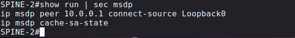
Notice that we use the unique (Loopback0) loopback addresses of the Spines here, not the anycast address! After the TCP session has been established, Spines send MSDP SA (Source Active) messages to each other notifying each other about a sender which wants to send multicast (the (S,G) states in the mroute table). So if the SPINE-1 receives PIM Register messages from LEAF-1 and LEAF-2 with the multicast group of 239.0.0.10 and 239.0.0.20, SPINE-1 sends an MSDP SA message to SPINE-2 over TCP to notify his peer about the senders, for the case SPINE-2 also has as (*,G) entries for these groups. So basically one RP knows about the senders, the other RP knows about the receivers, we connect them together via MSDP:
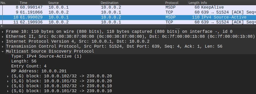
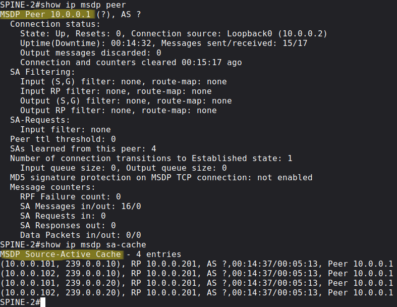
Lastly with the following show commands we can verify that the MSDP session is successfully established between the Spines, and also that they exchanged SA messages:
Phantom RP with PIM Bidir
While the previous Anycast implementation does load-balancing and works in an active-active fashion, Phantom RP is different, because under normal circumstances the Leaf switches only send multicast packets towards the "active" RP, the "backup" RP does not forward multicast packets by default. The convergence is based on the IGP convergence, because this time the Leaf switches send packets based on the "longest match prefix" towards the RP. First we enable PIM Bidir globally on all of the switches, and this time I configure the RP as bidirectional manually:
ip pim bidir-enableip pim rp-address 10.0.0.150 bidir
BiDir PIM does not use unicast PIM Register messages between the first-hop router and the RP, and does not use (S,G) PIM Join messages. We only use the (*,G) multicast state and shared trees which are rooted at the RP. So this also implies that the RP is always in the data plane, multicast traffic always flows through the RP. So we completely get rid of the source-tree and the (S,G) states, the advantage is that we only need one entry for all sources that are sending in a particular group - this is also useful when we have a lot of senders and receivers and we have scalability problems with a lot of (S,G) states. Unlike the Anycast RP implementation, session synchronization between the two RPs is not required this time.
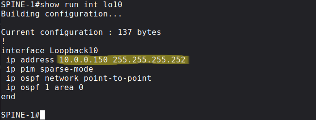
Next we create a new loopback on both Spines, and we assign the same 10.0.0.150 prefix to both, but with different prefix length this time. I use /30 on SPINE-1:
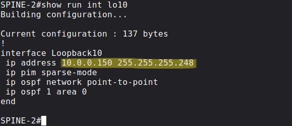
and /29 on SPINE-2:
As we did before we advertise these new prefixes into OSPF and enable PIM SM on them.
Pitfall: It's very important that OSPF by default advertises loopback addresses with the Loopback network type, which means it advertises everything with /32 prefix length, regardless of the actual mask configured on the loopback interface. So we have to change it to point-to-point. Without this both prefixes would be advertised as 10.0.0.150/32.
So the primary RP (SPINE-1) advertises longest match into OSPF, secondary RP (SPOKE-2) advertises second-longest match. This is the routing table of LEAF-1 with both prefixes:
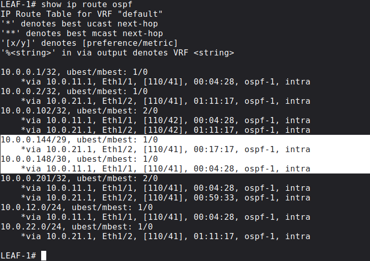
The Spine which has the longest match in the routing table, that will be the Spine we're going to build the shared tree towards. So with PIM BiDir we don't use the RP for control plane signalling, we use the RP as a routing vector: we build the tree towards the RP. If the primary RP fails, the secondary RP's address will be the longest match, and the Leaf switches send multicast towards the secondary RP. The time of the failover is simply based on the convergence time of OSPF.
We can also verify the mroute table on SPINE-1 which is the primary RP by default:
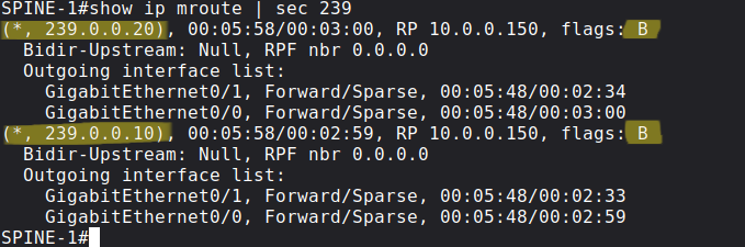
There are no (S, G) states anymore, we only have (*, G)s, the B flag also indicates that these are bidirectional multicast groups.
BGP EVPN
EVPN is a standards-based control plane mechanism which uses MP-BGP. EVPN is not VXLAN exclusive, we can also use EVPN with MPLS data plane for example. Instead of learning the MAC address in the data plane (like a normal switch would do and as what we've seen in the previous post), BGP EVPN provides an "active" mechanism. Instead of sending the traffic everywhere in the data plane, BGP advertisements are used to distribute the Layer-2 information of the connected MAC addresses to the remote Leaf switches. This "active" control plane minimizes multicast flooding which I've showed previously.
Before we start configuring BGP, let's enable the following features on all Leaf switches:
LEAF-1(config)# feature bgpLEAF-1(config)# nv overlay evpnLEAF-1(config)# feature fabric forwarding
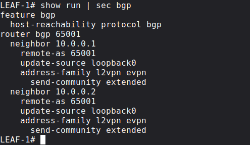
Now we can configure BGP and enable the l2vpn evpn address-family between the VTEPs. For scalability purposes we're going to use the Spines are Route Reflectors, the Leaf switches peer with both of Spines, but not with each other directly. Here is the configuration of LEAF-1 for example:
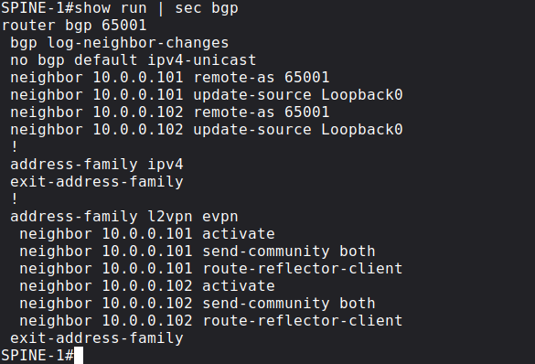
The BGP configuration of the other VTEP (LEAF-2) is exactly going to be exactly the same as the configuration of LEAF-1. Similarly both of the Spines are going to function as Route Reflectors with identical BGP configuration:
Next with the following commands we basically enable MAC address learning via BGP Updates (both of the Leaf switches have identical configuration in this regard):
LEAF-1(config)# do show run | sec ^evpnevpn vni 10010 l2 rd auto route-target import auto route-target export auto vni 10020 l2 rd auto route-target import auto route-target export auto
LEAF-1(config)# int nve 1LEAF-1(config-if-nve)# host-reachability protocol bgp
BGP generates NLRI advertisements, here with EVPN the prefix is not going to be an IPv4 address, it is going to be a MAC address. Whenever the Leaf switches receive an ARP message from the end hosts, they share the MAC address / IPv4 address of their connected end hosts with the other Leaf switches proactively. For example once LEAF-1 learns the MAC address of srv-01 from ARP messages, it generates a BGP Update message and tells the other Leaf switches that the MAC address of 'srv01' is reachable via LEAF-1 with the IP address 10.0.0.101.
Here we use the auto keyword for both the RD and the Route-Target as well, so we don't set them explicitly. We're prepending the RD to make the MAC addresses unique (theoretically 2 different customers can have the same MAC address). The RD is automatically derived from the Router-ID and an internal VRF identifier. We generate the RT values based on the ASN + the VNI number. This is how the remote Leaf figures out where the advertised MAC address belongs. All of the advertised MAC addresses are now in the BGP table (show bgp l2vpn evpn), but not necessarily in the FIB and in the MAC address table (show mac address-table). The Leaf switch only installs the MAC address into the MAC address table if we have the VLAN configured. Here is a BGP l2vpn evpn NLRI which LEAF-1 sends to the RR:
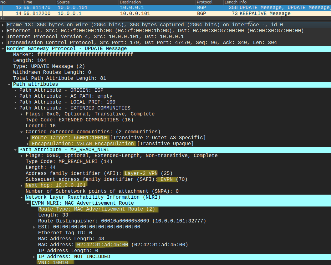
This is Type-2 MAC/IP advertisement: LEAF-1 (10.0.0.101) advertises that the MAC address of 'srv-01' is reachable via him. Notice that the IP address is not set in this case, LEAF-1 only advertises the MAC address, we'll see shortly that when we enable routing between the VLANs, the VTEPs will also set the IP address in the Type-2 advertisement. LEAF-1 sends this NLRI to the Reflectors, and they forward it to all of the remote Leaf switches.
If the BGP L2VPN EVPN NLRI comes in on the other Leaf switch, the Leaf takes a look at the RT value, if that doesn't match with the local mapping with the VNI, it discards the route. Basically the concept is the same as with VRFs and MPLS L3VPNs. Here is the BGP table of LEAF-1:
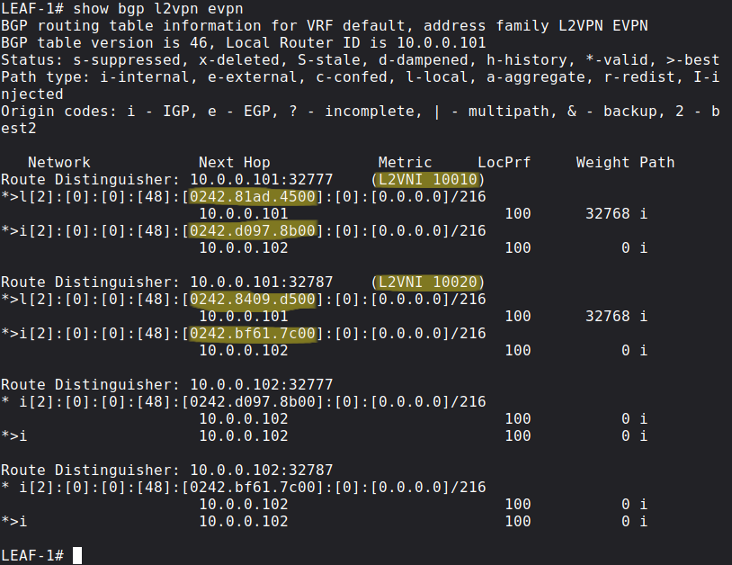
Notice that LEAF-1 learned the MAC address of 'srv-03' (02:42:D0:97:8B:00) and 'srv-04' (02:42:BF:61:7C:00) via BGP, so it doesn't need to use multicast flooding if some of its connected host wants to send traffic to the remote servers.
Inter-VXLAN routing with Symmetric IRB and Anycast Gateway
Now let's enable routing between the two Leaf switches, specifically we want to establish communication between srv-01 - srv-04 and between srv-02 - srv-03. First I assign a default gateway to the servers, which will point to the last usable address (.254) in each subnet:
root@srv-01:~# route add default gateway 192.168.10.254root@srv-02:~# route add default gateway 172.16.0.254root@srv-03:~# route add default gateway 192.168.10.254root@srv-04:~# route add default gateway 172.16.0.254
With EVPN Integrated Routing and Bridging (IRB) we have to options: we can either use asymmetric IRB or symmetric IRB. I'll show the symmetric option here, which is a the preferred method. With symmetric IRB we need just one shared segment everywhere, instead of all VNIs which require routing. This helps reducing the ARP cache and CAM table size. With symmetric IRB the ingress VTEP doesn't need to know the destination VNI for inter-VNI routing. VTEPs don't need to learn and maintain MAC address information for VNIs for which it doesn't have local hosts.
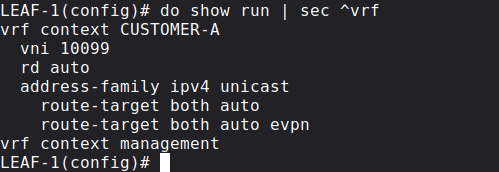
First we create a new VRF on all of the Leaf switches, in this example let's say that all of the servers belong to CUSTOMER-A:
Next besides the SVIs for the corresponding VLANs we create a new Layer 3 VNI:
vlan 99 vn-segment 10099interface Vlan99 no shutdown vrf member CUSTOMER-A ip forwardinterface Vlan10 no shutdown vrf member CUSTOMER-A ip address 192.168.10.254/24 fabric forwarding mode anycast-gatewayinterface Vlan20 no shutdown vrf member CUSTOMER-A ip address 172.16.0.254/24 fabric forwarding mode anycast-gateway
Routed traffic will use the new L3 VNI which has been associated with the VRF. Each customer VRF is mapped to this new unique Layer 3 VNI. The same L3 VNI - VRF mapping must be present on every VTEP where CUSTOMER-A has servers.
In this example we'll use VNI 10099 for the shared segment. On the new SVI int vlan 99we just have the ip forward: this is because we don't need an IP address on this new interface, we just enable IP processing with this command, we're routing through this interface, we're never sending packets to the interface itself.
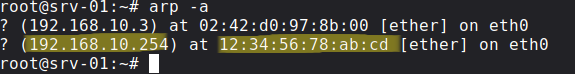
Next I assign the MAC address to the anycast gateway, we use the same MAC address on all Leaf switches:
fabric forwarding anycast-gateway-mac 1234.5678.abcd
This allows us host mobility: the end hosts can move freely between the VTEPs without changing their IP address or default gateway (this is also what we use in SD-Access). Now if any of the servers send an ARP Request for their default gateway, the Leaf switches return the MAC address we just configured above:
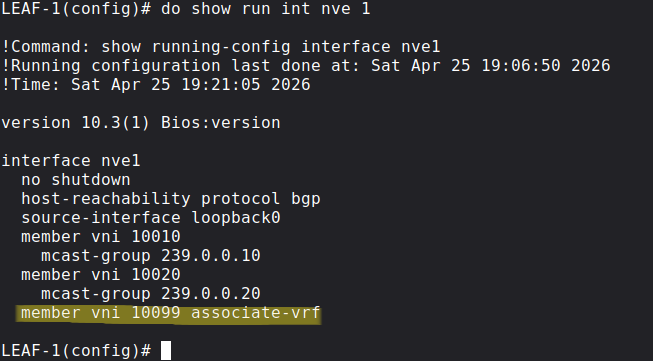
Next we associate the new L3 VNI with the NVE interface with the following command:
Just like in the previous example we'll use BGP EVPN as the control plane for MAC/IP address distribution, but we have to enable BGP EVPN advertisement generation for CUSTOMER-A under the BGP config:
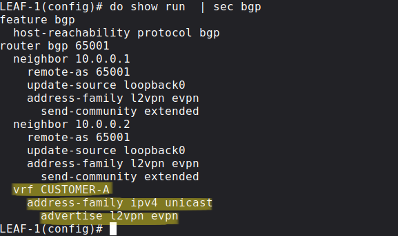
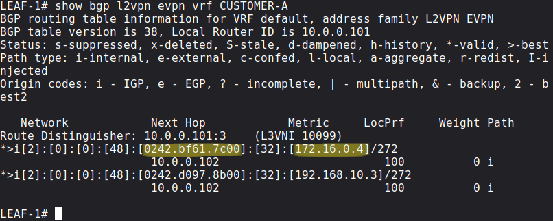
Similarly to the previous example, BGP EVPN advertisements are generated whenever the Leaf switch learns an address via ARP messages from end hosts, and the Type-2 NLRIs are distributed to remote VTEPs, but this time the NLRI contains not just the MAC address but also the IP address of the end host. Let's take a look how the NLRI looks like that LEAF-2 generates and sends to LEAF-1 (through the route reflectors):
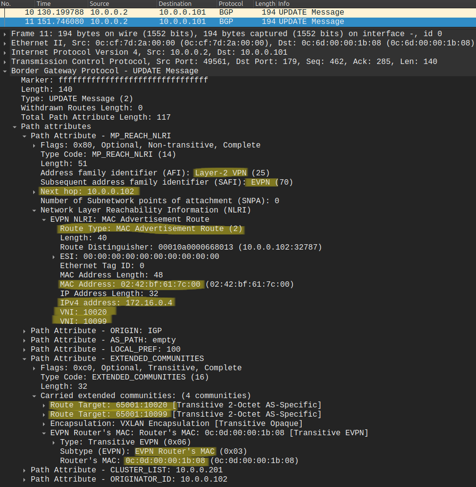
The BGP Update contains a lot of information! I tried to highlight what is important for us now: besides the MAC address of srv-04 (02:42:BF:61:7C:00), this one also contains the IP address (172.16.0.4). Besides the source VNI 10020 (VLAN 20), LEAF-2 also assigns the new shared L3 VNI (10099) to the NLRI. We add a new export route-target for the L3 VNI (65001:10099), so that LEAF-1 will be able to import it, because we configured the VRF identically on both Leaf switches:
So let's try to ping srv-04 from srv-01:
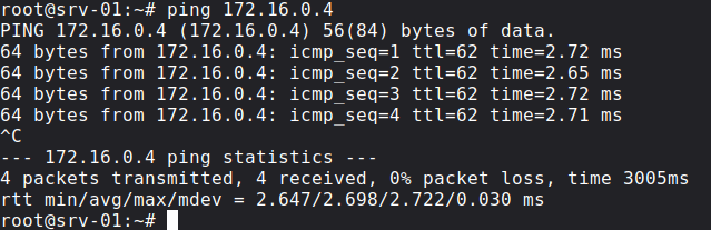
It works, let's also take a look at the data plane and the ICMP Echoes:
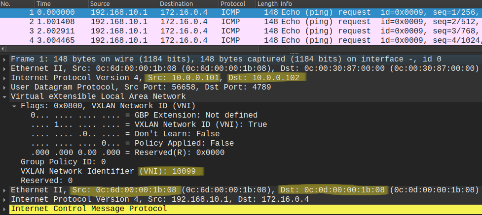
Notice that the packet capture only contains the Echo Requests and not the Echo Replies, this is not because we dropped the packets, but because the underlying IGP. Leaf switches use ECMP between the two Spines, so while the Echo Requests went through SPINE-1, the Replies came back through SPINE-2, and I captured the packets between LEAF-1 and SPINE-1. Notice that the packet is now tagged with the new L3 VNI (10099) in the VXLAN header, all routed traffic will be encapsulated with this header. In the outer header the source IP and the destination IP is the loopback of LEAF-1 and LEAF-2 respectively, the same what we've seen with Layer 2 forwarding in the previous post. But in the inner Ethernet header we cannot just use the the MAC address of srv-04 as the destination this time, because we're forwarding packets between subnets. The inner destination MAC address has to be the MAC address of LEAF-2 (0C:0D:00:00:1B:08 in our example). How does LEAF-1 learn this address? Look at the BGP Update above: it is included with the NLRI as an extended community. So BGP EVPN handles everything.
Finally let me share my pcaps and the MAC address table of the Leaf switches of this lab for further learning, packet analysis and packet walkthrough, you can find it in this Github repo. Lastly I would like to recommend the following Cisco Live! presentations for further learning as well, I used these to understand VXLAN and to create this lab:
BRKDCN-3966 - VXLAN BGP EVPN Fabrics: A Day in the Life of a Packet
BRKENS-2092 - Building Scalable VXLAN BGP EVPN Fabrics for Enterprise networks