Implementing VXLAN on NX-OS part 1: basic VXLAN operation, multicast flood and learn
VXLAN is tunneling protocol, which is mainly used in data centers. With VXLAN we can encapsulate the whole Ethernet frame in a UDP datagram. VXLAN is not supported on regular Cisco IOS-XE switches, so I use the Nexus 9000v switch in this example:
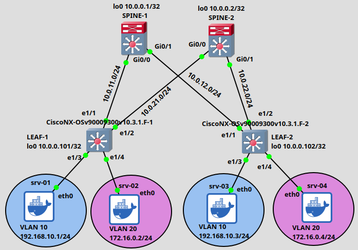
Nexus switches are very resource-heavy, they need a lot of RAM (at least 8 Gigs for a single box!), so I only use 2 Leaf and 2 Spine switches in this example. Moreover I use regular Cisco IOS routers instead of Nexus switches for the Spines. We will see that the Spines don't need to understand VXLAN, they only need to run unicast, and multicast routing, supporting PIM SM and OSPF as the routing protocol in our example. But keep in mind that in a regular DC environment the Spines are also Nexus switches. The 4 servers are very lightweight, they are Docker containers running Ubuntu Linux. Our goal is that the servers in the same VLAN residing in the same subnet should be able to communicate with each other. But at this point devices in different VLANs won't be able to reach each other. Later we'll also implement inter-VXLAN routing using symmetric IRB and anycast gateways.
Notice that we don't run STP for loop prevention at all between the Spines and the Leafs, the interfaces between the Spines and Leafs are routed ports (with no switchport configured). STP won't block redundant paths, we can use ECMP and load-balancing.
This is called Clos or Spine-Leaf architecture in the DC environment: we can have as many Spine and Leaf switches as we want. The main principle is that each Leaf switch should be connected to each Spine, and the Leafs are not connected with each other directly. This architecture is very scalable, we can easily add new Leaf switches to an existing topology, and provides high performance and low latency for east-west traffic (from Leaf to another Leaf).
Configuring the Leaf switches
Leaf switches have very similar role to the PEs (Provider Edge) or LERs (Label Edge Router) with MPLS VPNs or the RLOCs with LISP, they are the VTEPs (Virtual Tunnel Endpoint), they perform the VXLAN encap- and decapsulation. On a real Nexus devices the encap/decapsulation processes are usually hardware-accelerated.
Before we start configuring anything let's enable the following features on the Leaf switches:
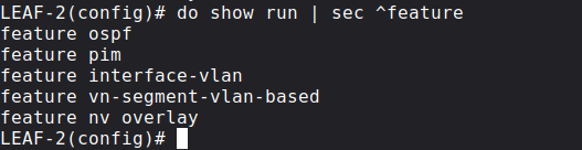
We basically turn on OSPF, PIM and VXLAN overlay on the Leafs. We don't need the interface-vlan feature at this point, because first we only configure VXLAN Bridging, only the servers in the same subnet will be able to reach each other at first.
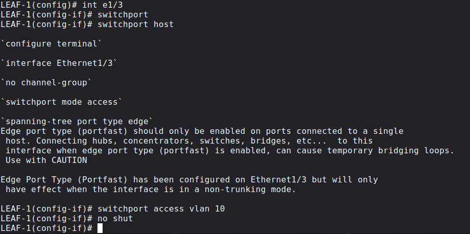
Next let's configure the customer-facing (i.e. interfaces towards the servers) interfaces: they are regular switchports, assigned to a single VLAN. srv-01 and srv-03 are in VLAN 10, and srv-02 and srv-04 are in VLAN 20. With the switchport host command we configure them as access ports, and enable STP Portfast as well, so these ports won't generate TCNs on the Leaf switches.
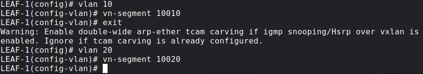
Next we define the VLANs locally on each Leaf switch and map a VXLAN NVI (VXLAN Network Identifier) to each VLAN. Unlike regular VLANs, instead of having the 12 bit VLAN ID space, VXLAN uses 24 bit VNIs. VLANs are locally significant on each Leaf switch, VNIs are globally significant for a whole VXLAN segment. Here we map VLAN 10 to VNI (sometimes called VNID) 10010 and VLAN 20 to VNI 10020 on both Leaf switches.
Think of the VXLAN segment as a broadcast domain in a L2 network: If srv-01 sends an ARP Request, who can receive it? Devices in the same VLAN on the local switch, and in this case srv-03 will also receive it because VLAN 10 on the remote side is also mapped to VNI 10010.
Multi-tenancy is possible: VLAN numbers and IP addresses configured on end hosts are locally significant, only VNIs need to be globally significant now, but we have more than 16 millions VNIs this time since we represent it in a 24 bit field of a new VXLAN header.
Routing and Multicast between Spine and Leaf switches
As I briefly mentioned before we establish an OSPF and PIM adjacency between the Spine and Leaf switches. I won't explain the OSPF and PIM configuration in details, I wrote many posts about how unicast and multicast routing works. For example here is the configuration of LEAF-1 e1/1 interface which is connected to SPINE-1:
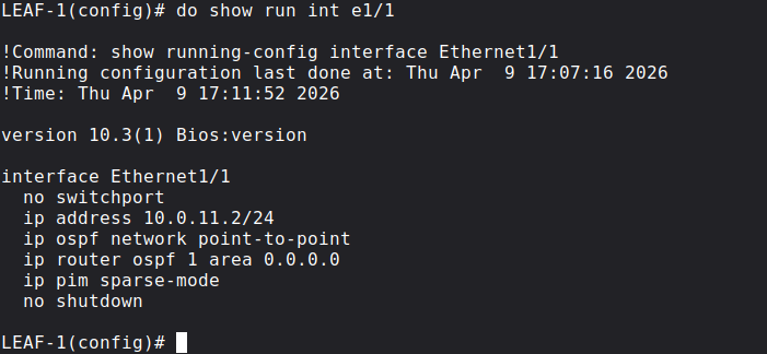
Very basic and straightforward. The only thing which is worth to mention is that on NX-OS we also have to active the OSPF process globally with the following command:
LEAF-1(config)# router ospf 1
Unlike on IOS, it is not enough to just activate the OSPF process on the interfaces, we also have to do it globally. At the end, all of the Spine switches should have an OSPF and PIM adjacency with all of the Leaf switches. Before we go forward let's verify this on SPINE-1:
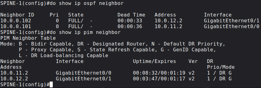
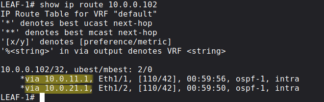
As I mentioned before, Leaf switches do load-balancing to reach the remote Leaf switches. For example in our case LEAF-1 sends packets towards both SPINE-1 and SPINE-2 to reach LEAF-2 since the OSPF costs are equal:
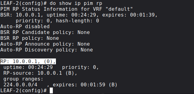
Configuring the RP for PIM Sparse Mode
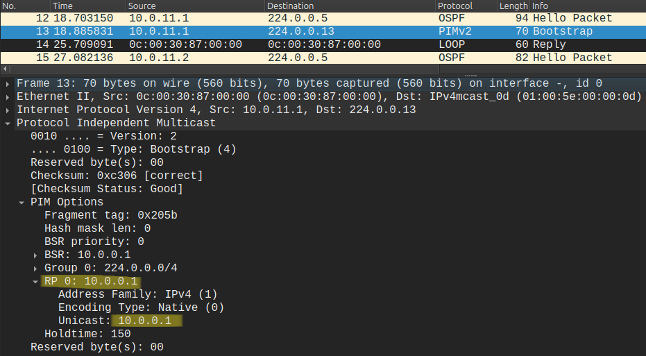
For PIM Sparse Mode to work properly, we have to designate a Spoke switch as the RP. I also won't explain it in details (see my previous post here), but we use BSR to advertise RP information. First we will configure a single RP on SPOKE-1, but later for redundancy purposes I will also show how we can implement Anycast RP with MSDP and PIM Bidir using a Phantom RP. So at this point let's advertise the IP address of the Loopback0 interface on SPOKE-1 as the BSR and also the RP address:
SPINE-1(config)#do show run | sec bsr-candidate|rp-candidateip pim bsr-candidate Loopback0 0ip pim rp-candidate Loopback0
Now this information is forwarded to the Leaf switches using the PIM Bootstrap messages like the one below:
NX-OS is very different than IOS-XE in this aspect for example, because the Leaf switches won't just accept this information by default. We have to tell the Leaf switches explicitly to use the PIM Bootstrap messages for RP information and to accept the RP which the Spoke is advertising using these commands:
LEAF-2(config)# ip pim bsr listen LEAF-2(config)# ip pim bsr forward
Now before we move forward, we should verify that all of the Leaf switches know who the RP is and where to send the PIM Join messages:
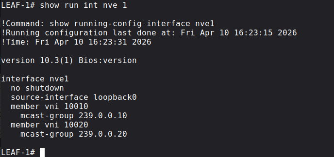
Creating the NVE interface on the Leaf switches
Next we create the nve interface on each Leaf switch. The NVE (Network Virtualization Edge) interface is a logical interface (like a GRE tunnel interface with IPsec VPNs) for the VTEPs. Basically we terminate the VXLAN tunnels here, this is where we do en/decapsulation.
Here we map a multicast group to each VNI for BUM replication. It's important that we use the same multicast groups on each Leaf for the same VNIs:
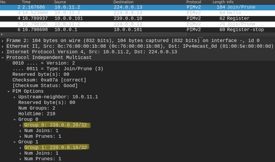
The moment we no shut the NVE interface, the Leaf switches send a (*, G) PIM Join message toward 10.0.0.1 for both 239.0.0.10 and 239.0.0.20 multicast groups:
We can also verify this on the RP: the RP should have a (*, G) entry for each multicast group we configured on the NVE interfaces, and in the OIL we should have all of the interfaces connected to each Leaf switch:
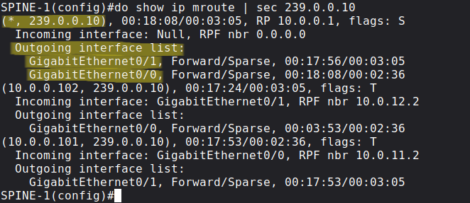
If we don't then there is something wrong with the underlay unicast/multicast routing, the overlay tunnels won't work properly.
VXLAN control plane options
The question is that how can LEAF-1 find the remote VTEP (in our case LEAF-2) to which it sends the Ethernet frame from srv-01, encapsulated in a UDP datagram? How can LEAF-1 learn that srv-03 is connected to LEAF-2?
If srv-01 in our example wants to reach srv-03, first it sends an ARP Request since srv-03 is in the same subnet (srv-01 doesn't know the MAC address of srv-03 at first). How will this ARP Broadcast message forwarded by LEAF-1? We have basically 3 options:
- Ingress replication
- Multicast flood and learn -> we use this in this lab
- MP-BGP EVPN
Ingress replication is the least efficient method. From the Leaf switch we send out unicast packets towards each Spine switch. Here in this example we only have 2, but imagine that we have dozens of Spine and Leaf switches in a DC environment, which means we send out dozens of unicast packets for a single ARP Broadcast. We can see that this method is not very efficient, does not scale very well, especially if we have a lot of switches. Instead of sending out a lot of unicast packets, with Multicast Flood & Learn we send out a single multicast packet, Leaf switches which have joined the multicast group receive the multicast packet. We use different multicast groups for different VNIs. We will use this method in our example in this post. Lastly we will also see how BGP EVPN works which is even more efficient, highly scalable method. We basically offload our ARP-cache into BGP routing, when we use BGP EVPN as the control plane.
Packet walkthrough
So we issue a simple ping from srv-01 to srv-03. Because srv-03 is in the same subnet as srv-01, srv-01 doesn't need to send the packet to its default gateway. It knows that it can reach srv-03 directly. But srv-01 doesn't know the MAC address of srv-03, so it sends an ARP Request to FF:FF:FF:FF:FF:FF broadcast. LEAF-1 floods this frame to all other switchports assigned to VLAN 10 (there aren't any in our example) and encapsulates the ARP frame into a multicast IP packet and sends it to 239.0.0.10, because LEAF-1 doesn't know where srv-03 is located at this point.
VTEPs also strip off the 802.1Q VLAN tag and encapsulate the packet with a new VXLAN header including the VNI: LEAF-1 encapsulates this ARP broadcast frame into a UDP datagram using a well-known destination port of 4789, and adds a VXLAN header with the VNI 10010 included, because we assigned VNI 10010 previously to VLAN 10:
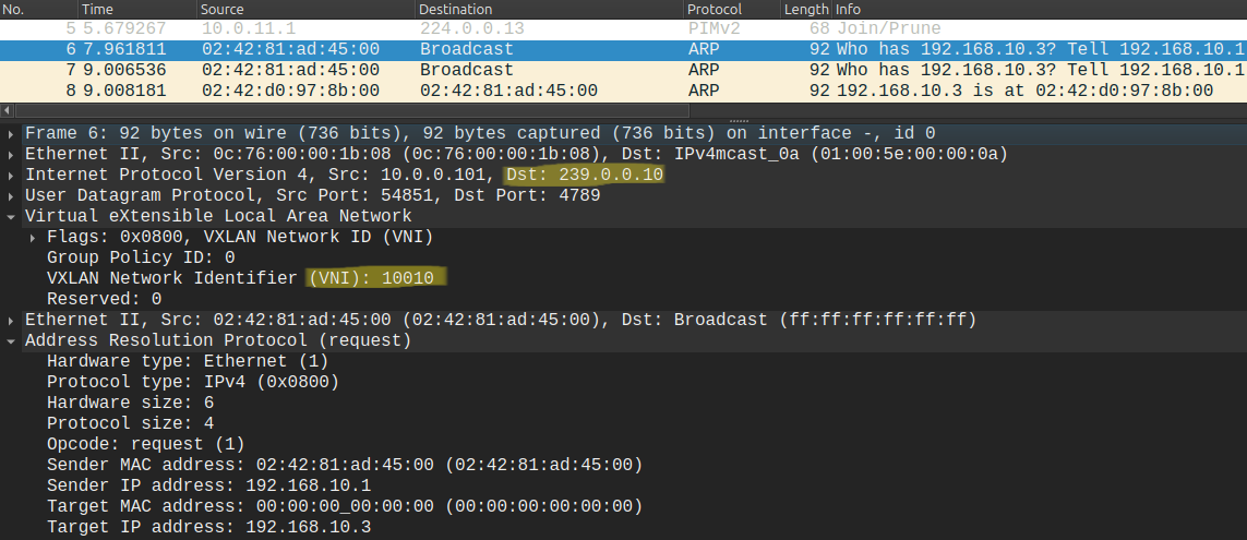
Because the remote VTEPs have also joined this group the RP forwards this packet to every other VTEP, LEAF-2 in our example. Notice that the source IP address is 10.0.0.101, the loopback address of LEAF-1, this is what we configured with the source-interface lo0 command under the NVE interface on the Leaf switch.
LEAF-2 receives this packet, decapsulates it, and because VNI 10010 is also configured on LEAF-2, it strips off the VXLAN header and floods this ARP broadcast frame out of all of his switchports configured in VLAN 10.
srv-03 receives the ARP Request and answers with an ARP Reply. Remember ARP Replies are UNIcast, what does LEAF-2 do with this unicast frame? It doesn't need to send it to the multicast group address anymore, because LEAF-2 learned that 02:42:81:AD:45:00 (the MAC address of srv-01) is reachable via 10.0.0.101 (the loopback address of LEAF-1). So it sends it as unicast:
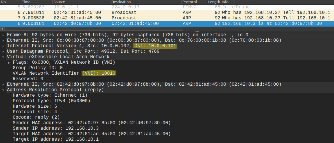
From this packet LEAF-1 also learns that 02:42:D0:97:8B:00 (the MAC address of srv-03) is reachable via 10.0.0.102 (the loopback of LEAF-2). As the name says: the Leaf switches flood the unkown and broadcast addresses to the multicast group address to learn the remote VTEP where the destination host is located. So to summarize: unicast frames are tunneled in unicast, multicast is tunneled in multicast, and broadcast and unknown unicast (i.e. ARP) are also tunneled in MULTIcast.
MAC address learning and verification
How does a regular L2 switch work? It learns MAC addresses and maps the MAC addresses to switchports in his CAM table. The same is true for the Leaf switches, except that we don't map the MAC addresses to L2 switchports, but to the loopback addresses of other Leaf switches. So on LEAF-1 we say that srv-01 is reachable via e1/3 and srv-03 is reachable via LEAF-2 (10.0.0.102):
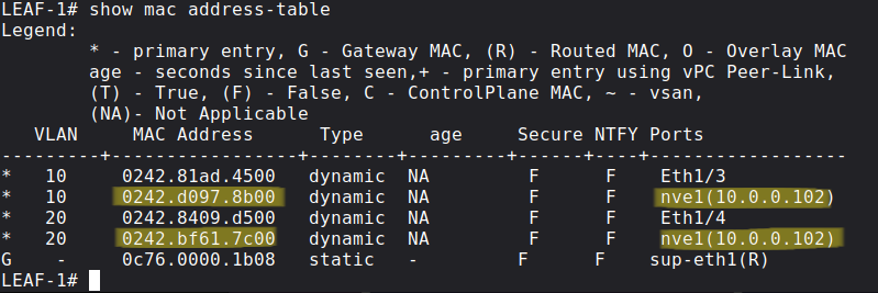
So if the MAC address is mapped to the nve1 interface on the last column, it means that the Leaf needs to VXLAN encapsulate the frame and send it the the IP address of the remote VTEP.
Lastly we can use the following show commands for verification:
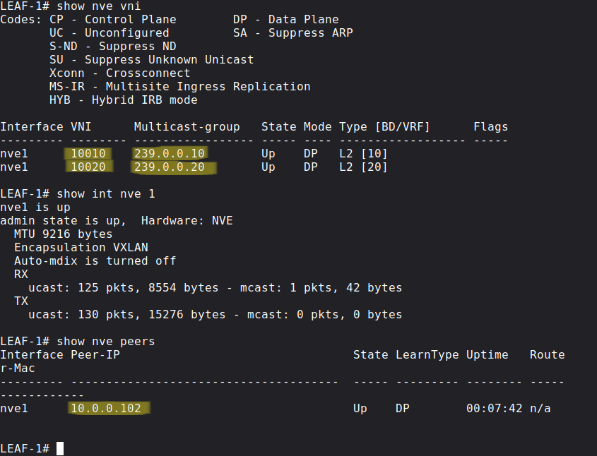
The first one is just a brief summary which VLANs are mapped to which VNIs and which multicast group addresses they are using. In the last one we can confirm that LEAF-1 discovered 10.0.0.102 (LEAF-2) and can send VXLAN-encapsulated packets, the packet count and bytes should increase when we send traffic from srv-01 to srv-03.